The cylinder head gasket is replaced if it is damaged
The main signs of a damaged cylinder head gasket:
- – insufficient compression (below 1 MPa (10 kgf/cm 2)) in one or more cylinders;
- – gas breakthrough into the cooling system (bubbling, foaming of liquid in the radiator, rapid drop in the liquid level in the expansion tank in the absence of external leaks);
- – coolant entering the lubrication system (emulsion on the oil level indicator, stratification of oil drained from the crankcase - especially noticeable in a transparent container);
- – oil entering the cooling system (oil film on the surface of the liquid in the expansion tank).
You will need: a torque wrench, screwdriver, pliers, keys (regular and socket) "8", "10", "13", "17", "E-Torx" head.
- 1. Remove the cylinder head cover (see "Replacing the head cover gasket Niva Chevrolet").
- 2. Drain the liquid from the engine cooling system (see "Replacing the cooling fluid Niva Chevrolet").
- 3. Reduce the pressure in the fuel system (see "Reducing the fuel pressure of the Niva Chevrolet").
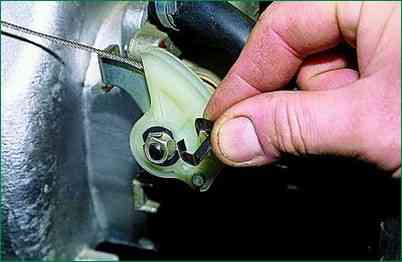
4. Disconnect the throttle cable from the throttle assembly and receiver.
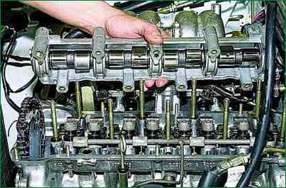
5. Remove the bearing housing together with the camshaft from the cylinder head studs (see "Replacing the hydraulic valve lifters of the Niva Chevrolet").
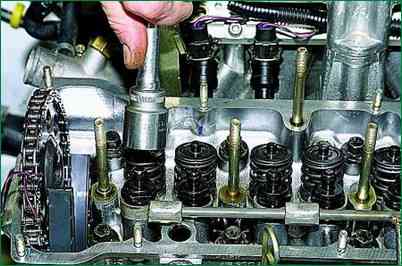
6. Remove the valve drive levers, unscrew all the hydraulic bearings of the levers from the cylinder head holes
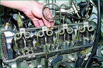
7. Remove the oil supply ramp to the hydraulic mounts.
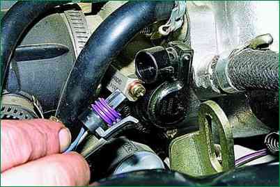
8. Disconnect the wiring harness connector from the throttle position sensor
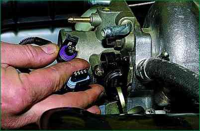
9. Disconnect the wiring harness connector from the idle speed control valve
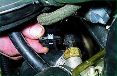
10. Disconnect the wiring harness connector from the engine management system coolant temperature sensor.
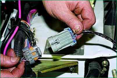
11. Disconnect the injector wiring harness connector.
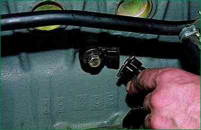
12. Disconnect the wiring harness from the knock sensor.
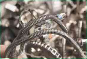
13. Move the engine harness to the side.
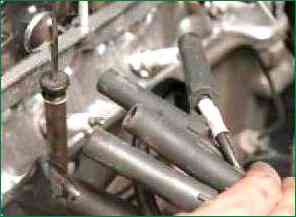
14. Disconnect the wires from the spark plugs.
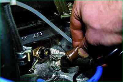
15. remove the protective cap and disconnect the wire from the coolant temperature gauge sensor.
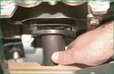
16. Disconnect the inlet pipe from the exhaust manifold.
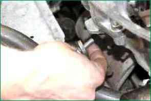
17. Unscrew the upper bolt securing the intake manifold spacer and, having loosened the lower bolt securing the spacer, move it to the side
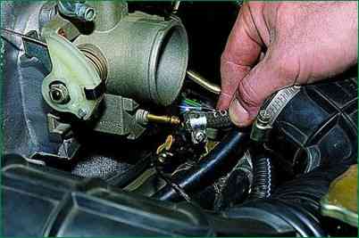
18. Loosen the clamp and disconnect the purge hose from the throttle assembly
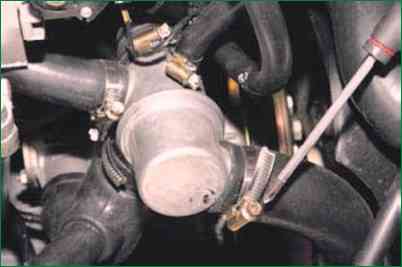
19. Loosen the clamps and disconnect the radiator hoses from the cylinder head pipe
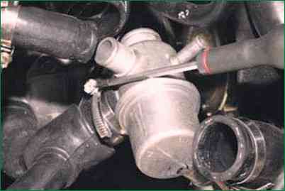
- 20. Loosen the clamp and disconnect the lower thermostat hose
- 21. Loosen the clamp and disconnect the thermostat side pipe hose
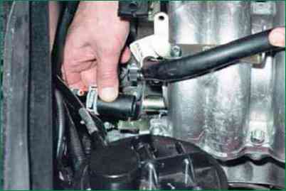
22. Loosen the clamp and disconnect the hose supplying liquid to the heater radiator from the cylinder head pipe.
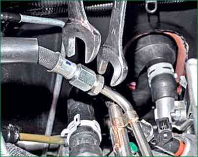
23. Loosen the fuel pipe nuts and disconnect the fuel supply and drain lines.
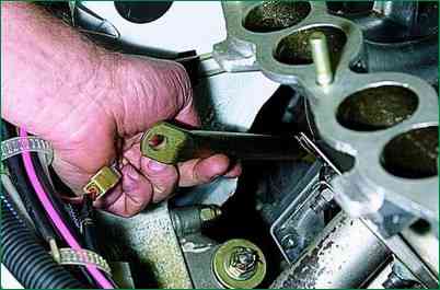
24. Remove the upper bolt securing the rear intake manifold strut, loosen the lower bolt of the strut and move it to the side.
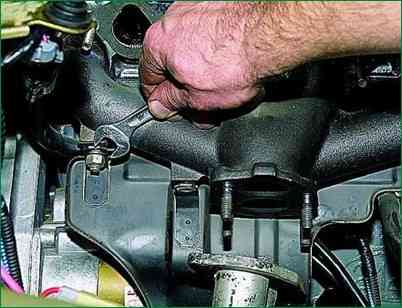
25. Remove the two nuts securing the starter heat shield
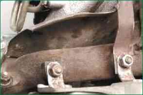
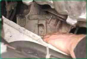
26. Move the shield to the side.
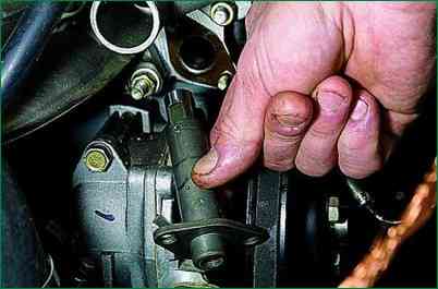
27. Remove the chain tensioner
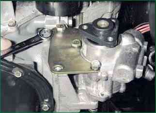
28. Disconnect the power steering pump bracket from the engine and move it aside together with the pump
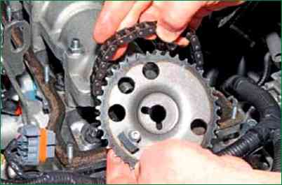
- 29. Remove the chain from the camshaft sprocket
- 30. Place it carefully on the tensioner shoe.
Make sure that the chain does not come out of engagement with the sprocket of the oil pump drive shaft.
It is best to tie the chain with wire.
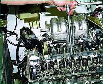
31. Unscrew the ten cylinder head mounting bolts.
The bolt heads are made for the "E-Torx" key, but if necessary, you can use a "13" head.
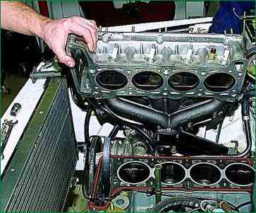
32. Remove the cylinder head.
It is more convenient to remove the cylinder head with an assistant, since it is quite heavy.
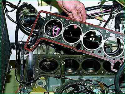
33. Remove the gasket located under the head.
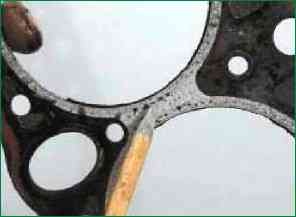
To determine the cause of the gasket failure, carefully inspect it.
On the edging of the gasket holes, traces of burnout will be visible between the combustion chambers of adjacent cylinders, between the combustion chamber and the channel of the cooling system jacket
- 36. or between the combustion chamber and the channel of the lubrication system.
- 37. Carefully clean the block surface from the remains of the old gasket.
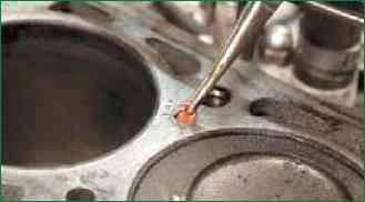
Remove foreign deposits from the cooling system jacket channels (if any).
The photo shows removing the old sealant.
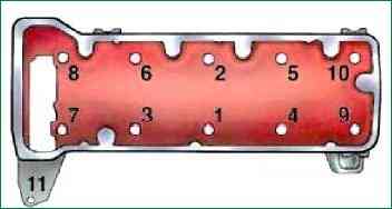
Install the cylinder head, centering it on the two guide bushings, screw in the bolts and tighten them in four steps in a specific sequence (as shown in the figure):
- – preliminary with a torque of 20.0 N m (2.0 kgf m);
- – tighten with a torque of 69.4–85.7 N m (7.1–8.7 kgf m);
- – tighten to an angle of 90 °;
- – finally tighten to an angle of 90 °.


