We remove the steering column switches for repairs, as well as for removing the steering column
The steering column switch consists of a connector secured with a clamp to the steering gear shaft bracket, and two switches.
The left switch turns on the turn signals and headlights, and the right one controls the operation of the windshield washers and wipers.
The switches are secured in the connector with latches.
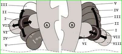
The positions of the switch levers are shown in Fig. 2, and the contacts closed in this case are given in the table.
The bold lines show the initial positions, the thin lines show the fixed positions, and the dotted lines show the non-fixed positions of the levers.
Contact closure at different positions of the steering column switch levers
Lever position - Closed contacts - Instruments switched on
Left lever
- I - Direction indicators off
- II* - 49a–49aR - Right turn indicators
- III - 49a–49aR - Right turn indicators
- IV* - 49a–49aL - Left turn indicators
- V - 49a–49aL - Left turn indicators
- I - 56–56b - Low beam headlights (with exterior lights on)
- VI* - 30–56a - High beam headlight warning
- VII - 56–56a - High beam headlights
Right lever
- I - 53e–53 - Windscreen wiper off
- II* - 53e–53 53a–j - Windscreen wiper (intermittent operation)
- III - 53e–53 53a–j - Windscreen wiper (intermittent operation)
- IV - 53a–53 - Windscreen wiper speed 1
- V - 53a–53b - Windscreen wiper speed 2 glass
- VI* - 53ah–W - Windscreen washer
- VII - 53ah–53H - Rear window wiper
- VIII* - 53ah–WH–53H - Rear window wiper and washer
* Non-fixed lever positions
Removing and installing the steering column switch
Disconnect the negative battery terminal.

Use a Phillips screwdriver to unscrew the two screws securing the lower part of the casing to the steering column bracket.

Unscrew the two screws connecting the lower and upper parts of the casing (the screws are installed in the recesses).

Use a Phillips screwdriver to unscrew the screw securing the casing to the steering column switch.

Unscrew one screw on each side connecting the lower and upper parts of the casing

Lowering the steering column adjustment handle, remove the lower part of the casing

Removing the rubber ring from the ignition switch

Removing the upper part of the casing

Squeeze the two clamps with your fingers

Remove the left steering column switch from the connector

Disconnect the wiring harness block from the switch
Also remove the right steering column switch.
To remove the switch connector, you need to remove the steering wheel (see the article - Removing the steering wheel of a Niva Chevrolet), then:

Press the lock of the wiring harness block of the panel with a screwdriver instruments

Remove the wiring harness from the connector socket

Use an 8 mm wrench to loosen tie bolt securing the connector to the steering column housing (shown on the removed column).

Removing the connector

When installing the connector, make sure that the recess on the connector matches the protrusion on the steering column housing
Install all parts in reverse order
")

")
")
")
")
")
")
")