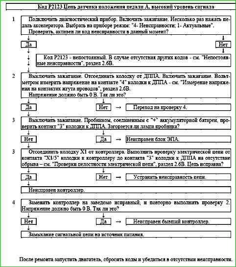
Code P2123 Pedal Position Sensor A Circuit High Input
Code P2123 is set if:
- - ignition is on;
- - accelerator pedal position sensor A (UPWG1ROH) signal is greater than 4.6 V for 0.2 s.
The malfunction indicator lamp comes on 5 s after the malfunction code has been set.
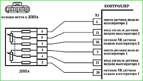
Description of tests
The sequence corresponds to the numbers on the map.
- 1 Using the diagnostic tool, it is checked whether the code P2123 is active at the time of diagnosis.
- 2 A voltage test is performed in the signal circuit of the DPPA A with the sensor disconnected. Voltage should be around 0 V.
- 3 The DPPA A ground circuit is checked for an open circuit.
- 4 The DPPA A signal circuit voltage is checked again after replacing the controller.
Diagnostic information
If a DPPA A circuit fault is detected, the engine management system will operate in emergency mode until the end of the current trip.
The following emergency modes are possible:
- - engine power limitation if the DPPA B circuit is in good condition;
- - idle speed if the DPPA A and DPPA B circuits are faulty.
The diagnostic tool in the mode "1 - Parameters; 6 - Additional Parameters; 3 - ADC Inputs" shows the DPPA A (UPWG1ROH) and DPPA B signals. (UPWG2ROH) in volts.
The signals of DPPA A and DPPA B increase proportionally to the accelerator pedal press. At any position of the accelerator pedal, the signal of DPPA A should be twice as large as the signal of DPPA B.
When the accelerator pedal is released, the signal of DPPA A should be in the range of 0.46…0.76 V, the signal of DPPA B should be in the range of 0.23…0.38 V.
To calculate the accelerator pedal position expressed as a percentage (WPED), the minimum signal from UPWG1ROH and 2 × UPWG2ROH is used.
Each time the ignition is turned on, the controller determines the zero position of the accelerator pedal. The 100% position is reached at a voltage of 2.30 V / 1.15 V from the DPPA A / DPPA B sensor.
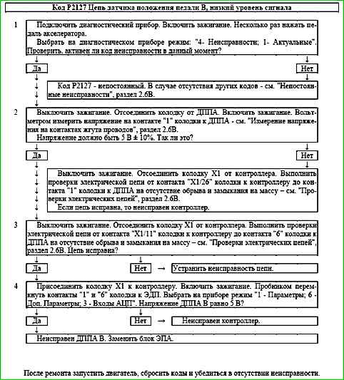
Code P2127 Pedal position sensor B circuit, low signal level

Code P2127 is set if:
- - ignition is on;
- - signal from accelerator pedal position sensor B (UPWG2ROH) is less than 0.16 V for 0.2 s.
The malfunction indicator lights up 5 s after the malfunction code has occurred.
Description of tests
The sequence corresponds to the numbers on the map.
- 1 Using the diagnostic tool, it is checked whether the P2127 code is active in moment of diagnostics.
- 2 The controller is checked: the reference voltage of 5 V from the controller should be supplied to contact "1" of the DPPA connector.
- 3 The signal circuit is checked for an open circuit or short circuit to ground.
- 4 The controller is checked: when contacts "1" and "6" of the DPPA connector are shorted using a tester, the DPPA B signal on the diagnostic device should change.
Diagnostic information
If a malfunction of the DPPA B circuit is detected, the engine management system will operate in emergency mode until the end of the current trip.
The following emergency modes are possible:
- - engine power limitation if the DPPA A circuit is serviceable;
- - idle speed if the DPPA A and DPPA circuits are faulty B.
The diagnostic device in the mode "1 - Parameters; 6 - Additional Parameters; 3 - ADC inputs" shows the signals of DPPA A (UPWG1ROH) and DPPA B (UPWG2ROH) in volts.
The signals of DPPA A and DPPA B increase proportionally to the pressing of the accelerator pedal. At any position of the accelerator pedal, the signal of DPPA A should be twice as large as the signal of DPPA B.
When the accelerator pedal is released, the signal of DPPA A should be in the range of 0.46 ... 0.76 V, the signal of DPPA B should be in the range of 0.23 ... 0.38 V.
To calculate the accelerator pedal position, expressed as a percentage (WPED), the minimum signal from UPWG1ROH and 2 × UPWG2ROH is used.
Each time the ignition is turned on, the controller determines the zero position of the accelerator pedal. The position 100% is achieved at a voltage of 2.30 V / 1.15 V from the DPPA A / DPPA B sensor.
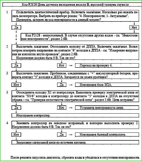
Code P2128 Pedal Position Sensor B Circuit High Voltage

Code P2128 is stored, if:
- - ignition is on;
- - signal from accelerator pedal position sensor B (UPWG2ROH) is greater than 2.3 V for 0.2 s.
The malfunction indicator lights up 5 s after the malfunction code has occurred.
Description of tests
The sequence corresponds to the numbers on the map.
- 1 Using the diagnostic tool, it is checked whether the P2128 code is active at the time of diagnostics.
- 2 The voltage in the signal circuit of the accelerator pedal position sensor B is checked with the sensor disconnected. Voltage should be around 0 V.
- 3 The DPPA B ground circuit is checked for an open circuit.
- 4 The DPPA B signal circuit voltage is checked again after replacing the controller.
Diagnostic information
If a DPPA B circuit fault is detected, the engine management system will operate in emergency mode until the end of the current trip.
The following emergency modes are possible:
- - engine power limitation if the DPPA A circuit is in good condition;
- - idle speed if the DPPA A and DPPA B circuits are faulty.
The diagnostic tool in the mode "1 - Parameters; 6 - Additional Parameters; 3 - ADC Inputs" shows the DPPA A (UPWG1ROH) and DPPA B signals. (UPWG2ROH) in volts.
The signals of DPPA A and DPPA B increase proportionally to the accelerator pedal press. At any position of the accelerator pedal, the signal of DPPA A should be twice as large as the signal of DPPA B.
When the accelerator pedal is released, the signal of DPPA A should be in the range of 0.46…0.76 V, the signal of DPPA B should be in the range of 0.23…0.38 V.
To calculate the accelerator pedal position expressed as a percentage (WPED), the minimum signal from UPWG1ROH and 2 × UPWG2ROH is used.
Each time the ignition is turned on, the controller determines the zero position of the accelerator pedal. The 100% position is reached at a voltage of 2.30 V / 1.15 V from the TPPS A / TPPS B sensor.
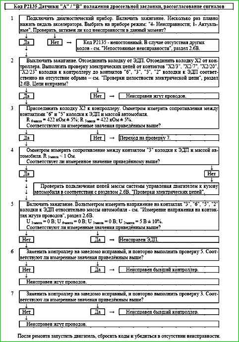
Code P2135 Throttle position sensors "A" / "B", signal mismatch
Code P2135 is entered if:
- - ignition is on;
- - signals of TPS A and TPS B differ by more than 6% within 0.3 s.
The malfunction indicator lights up 5 s after the malfunction code has occurred.
Description of checks
The sequence corresponds to the numbers on the map.
- 1 Using the diagnostic tool, it is checked whether the P2135 code is active at the moment diagnostics.
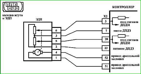
- 2 The TPS A and TPS B circuits are checked for open circuits.
- 3 The resistance of the TPS A and TPS B signal circuits (contacts "6" and "5") relative to the vehicle ground is measured.
- 4 The resistance of the TPS ground circuit (contact "1") relative to the vehicle ground is measured.
- 5 The voltage in the TPS circuits relative to the vehicle ground is measured.
- 6 The voltage in the TPS circuits relative to the vehicle ground is measured again with the controller replaced.
- 7 The resistance of the TPS A and TPS B signal circuits (contacts "6" and "5") relative to the vehicle ground is measured again with the controller replaced.
Diagnostic information
The diagnostic tool is in mode "1 - Parameters; 6 - Additional Parameters; 3 - ADC inputs" shows the signals of TPS A (UDKP1) and TPS B (UDKP2) in volts.
When the throttle valve is opened, the TPS A signal increases, the TPS B signal decreases.
When the throttle valve is fully closed, the TPS A signal should be in the range of 0.3 ... 0.6 V, the TPS B signal should be in the range of 4.4 ... 4.7 V.
The sum of the TPS A and TPS B signals should be equal to (5 ± 0.1) V at any throttle position.
The controller recalculates the voltage of the TPS A and TPS B signals into a percentage of throttle opening.
The diagnostic tool is in the "1 - Parameters; 1 - General view" displays the percentage of WDKBA throttle valve opening, which is calculated as the arithmetic mean of the signals of TPS A (%) and TPS B (%). 0% corresponds to with the throttle valve fully closed. 100% corresponds to the maximum throttle opening.
The signals from TPS A (%) and TPS B (%) are used to monitor the mismatch.
If a mismatch between the signals from TPS A and TPS B is detected, the engine management system will operate in emergency mode until the end of the current trip.
The following emergency modes are possible:
- - limiting engine power if the controller has determined which sensor is faulty;
- - de-energizing the throttle actuator and limiting engine speed (2500 rpm) if the controller does not trust the signals from both sensors.
If the throttle actuator is de-energized, the throttle valve is held in the Limp home position (7-8%) using the direct and return springs.
In case of replacement ECM or ECU controller, or resetting the controller using a diagnostic tool (mode "5 - Additional tests; 1 - ECU reset with initialization"), it is necessary to perform the throttle valve zero adaptation procedure.
To do this, with the vehicle stationary, turn on the ignition, wait 30 seconds, turn off the ignition, wait for the main relay to disconnect.
Adaptation will be interrupted if:
- - the engine is cranking;
- - the vehicle is moving;
- - the accelerator pedal is pressed;
- - the engine temperature is below 5 °C or above 100 °C;
- - the ambient air temperature is below 5 °C.
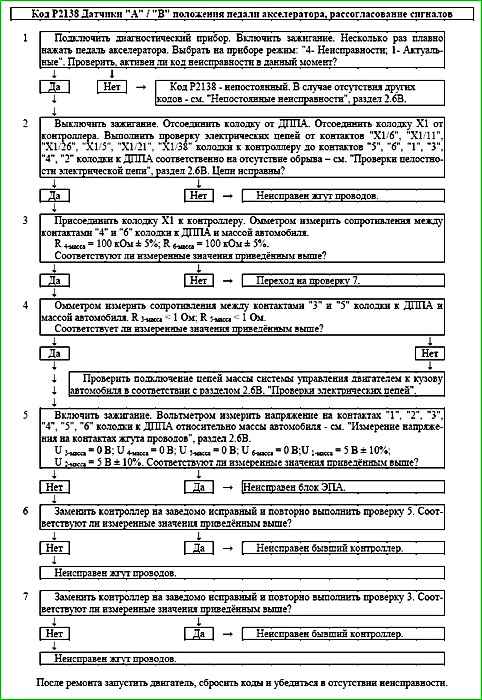
Code P2138 Accelerator pedal position sensors "A" / "B", signal mismatch

Code P2138 is set if:
- - ignition is on;
- - the half-scale signal from the accelerator pedal position sensor (UPWG1ROH/2) and the signal from the accelerator pedal position sensor B (UPWG2ROH) differ by the threshold value for 0.25 s.
The malfunction indicator lights up 5 s after the malfunction code has occurred.
Description of tests
The sequence corresponds to the numbers on the map.
- 1 Using the diagnostic tool, it is checked whether the P2138 code is active at the time of diagnostics.
- 2 The circuits of the DPPA A and DPPA B are checked for an open circuit.
- 3 The resistance of the signal circuits of the DPPA A and DPPA B (contacts "4" and "6") relative to the vehicle weight.
- 4 The resistance of the ground circuit of DPPA A and DPPA B (contacts "3" and "5") relative to the vehicle weight is measured.
- 5 The voltage in the DPPA circuits relative to the vehicle weight is measured.
- 6 The voltage in the DPPA circuits relative to the vehicle weight is measured again with the controller replaced.
- 7 The resistance of the signal circuits of DPPA A and DPPA B (contacts "4" and "6") relative to the vehicle weight is measured again with the controller replaced.
Diagnostic information
If a mismatch between the signals of DPPA A and DPPA B is detected, the engine management system will operate in emergency mode until the end of the current trip.
The diagnostic tool is in the mode "1 - Parameters; 6 - Additional Parameters; 3 - ADC inputs" shows the signals of DPPA A (UPWG1ROH) and DPPA B (UPWG2ROH) in volts.
The signals of DPPA A and DPPA B increase proportionally to the pressing of the accelerator pedal.
At any position of the accelerator pedal, the signal of DPPA A should be twice as large as the signal of DPPA B.
When the accelerator pedal is released, the signal of DPPA A should be in the range of 0.46 ... 0.76 V, the signal of DPPA B should be in the range of 0.23 ... 0.38 V.
To calculate the accelerator pedal position, expressed as a percentage (WPED), the minimum signal from UPWG1ROH and 2 × UPWG2ROH is used.
Each time the ignition is turned on, the controller determines the zero position of the pedal accelerator. The 100% position is reached at a voltage of 2.30 V / 1.15 V from the DPPA A / DPPA B sensor.
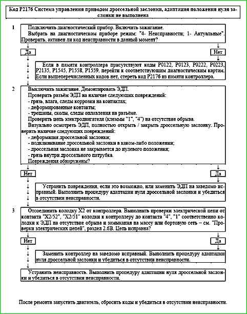
Code P2176 Throttle actuator control system, adaptation of the zero position of the valve is not performed

Code P2176 is entered if:
- - ignition is on;
- - adaptathrottle position zero calibration has never been performed.
The malfunction indicator lights up 5 s after the malfunction code has occurred.
Description of tests
The sequence corresponds to the numbers on the map.
- 1 Using the diagnostic tool, check whether the P2176 code is active at the time of diagnosis. If the code is inactive and at the same time there are no codes P0122, P0123, P0222, P0223, P2135, P1545, P1558, P1559 in the controller memory, then it is necessary to erase the code P2176 using a diagnostic tool.
- 2 The mechanical and electrical components of the throttle pipe are checked.
- 3 The control circuits of the electric throttle valve drive are checked.
Diagnostic information
If fault P2176 is detected, the engine management system will operate in emergency mode until the end of the current trip:
- - the electric throttle valve drive is de-energized;
- - engine speed limitation (up to 2500 rpm depending on the pedal position accelerator).
The diagnostic tool in the "1 - Parameters; 1 - General view" mode displays the percentage of opening of the WDKBA throttle valve.
When the ignition is turned on, the controller performs:
- - return spring test;
- - check of the valve position with the electric drive de-energized;
- - adaptation of the zero position of the throttle valve;
- - direct spring test.
If the controller is new (the adaptation is carried out for the first time), then all the above procedures are performed immediately after turning on the ignition for 1.5 seconds.
If the controller was taught earlier, then immediately after turning on the ignition the return spring test is performed.
The remaining procedures will be performed within the next 30 seconds, if none of the conditions:
- - the engine does not turn over;
- - the car does not move;
- - the accelerator pedal is not pressed;
- - the engine temperature is above 5 °C and below 100 °C;
- - the ambient air temperature is above 5 °C.
Code P2176 indicates that the first training of the controller was interrupted for the following reasons:
- - violation of the conditions for carrying out adaptation (see above);
- - throttle body malfunction;
- - wiring harness malfunction;
- - controller malfunction.
If the throttle actuator is de-energized, the throttle valve is held in the Limp home position (7-8%) by the direct and return springs.
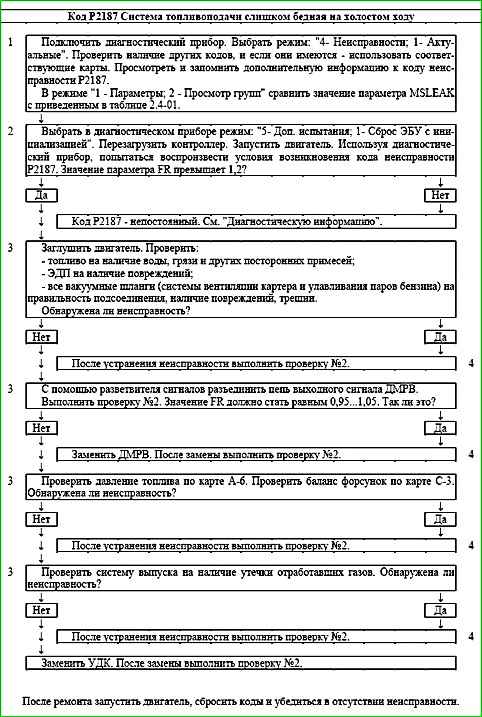
Code P2187 Fuel injection system too lean at idle
Code P2187 is set if:
- - the engine is running;
- - fuel supply control is carried out in the feedback mode based on the oxygen sensor signal (B_LR = "Yes");
- - the fuel supply adaptation function is activated (B_LRA = "Yes");
- - the MSLEAK parameter value goes beyond the upper limit of the permissible range (more 5).
The malfunction indicator lights up on the 3rd trip after a persistent malfunction has occurred.
Description of checks
The sequence corresponds to the numbers on the map.
- 1 The diagnostic information is analyzed.
- 2 With the engine running, the diagnostic tool simulates the conditions for the occurrence of the malfunction.
- 3 The systems and components whose malfunction may lead to the occurrence of the code are checked.
- 4 When repeating check No. 2 after eliminating the possible cause of the malfunction, the value of the FR parameter should not go beyond the range of 1±0.1.
Diagnostic information
An intermittent malfunction may be caused by the presence of the following malfunctions:
Unreliable connection of the contacts of the connectors of the ignition system harness, sensor and controller.
Inspect the sensor and controller connectors, harness pads for completeness and correctness of articulation, damage to the locks, presence of damaged contacts and quality of connection of contacts with the wire.
Incorrect route of the wire harness. Make sure that the branch to the sensor does not touch the elements of the exhaust system.
Harness damage.
Check the harness for damage. If the harness is outwardly normal, move the corresponding pad and harness, while observing the readings of the diagnostic device.
Unreliable grounding of the controller.
Check the reliability of the wire connection ignition system harness to the cylinder block. Make sure that the contacts are not contaminated.
UDC degradation. Replace UDC.
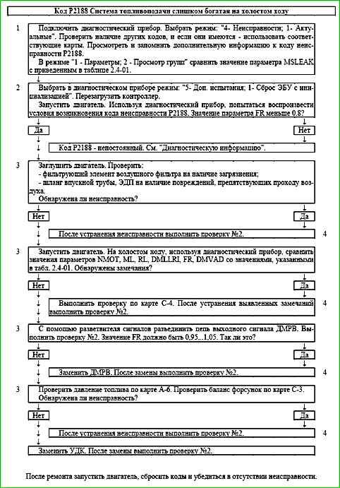
Code P2188 Fuel injection system too rich at idle

Code P2188 is set if:
- - the engine is running;
- - fuel supply is controlled in closed loop mode based on the signal from the control oxygen sensor (B_LR = "Yes");
- - the fuel supply adaptation function is activated (B_LRA = "Yes");
- - the value of the MSLEAK parameter goes beyond the lower limit of the permissible range (less than -5).
The malfunction indicator lights up on the 3rd trip after a persistent malfunction has occurred.
Description of tests
The sequence corresponds to the numbers on the map.
- 1 Diagnostic information is analyzed.
- 2 With the engine running, using the diagnostic tool the conditions for the occurrence of a malfunction are simulated.
- 3 The systems and components whose malfunction may lead to the occurrence of the code are checked.
- 4 When performing re-test No. 2 after eliminating the possible cause of the malfunction, the value of the FR parameter should not go beyond the range of 1±0.1.
Diagnostic information
An intermittent malfunction may be caused by the presence of the following malfunctions:
Unreliable connection of the contacts of the ignition system harness pads, sensor and controller.
Inspect the sensor and controller connectors, harness pads for completeness and correct articulation, damage to the locks, the presence of damaged contacts and the quality of the connection of the contacts with the wire.
Incorrect wiring harness route. Make sure that the sensor lead does not touch any exhaust system components.
Harness damage. Check the harness for damage. If the harness appears normal, move the corresponding connector and harness while monitoring the diagnostic tool.
Poor controller grounding. Check the ignition harness wires for proper connection to the cylinder block. Make sure the contacts are not dirty.
UDC degradation. Replace UDC.
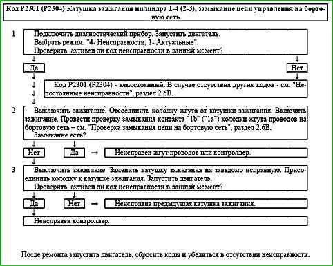
Code P2301 (P2304) Ignition coil cylinder 1-4 (2-3), control circuit short to on-board network

Code P2301 (P2304) is entered if:
- - the engine is running;
- - self-diagnosis has recorded a malfunction.
The malfunction indicator lights up 5 seconds after the malfunction code has occurred.
Description of tests
The sequence corresponds to the numbers on the map.
- 1 The presence of a permanent malfunction is checked.
- 2 The presence of a short circuit to the on-board network of the ignition coil control circuit is checked.
- 3 The serviceability of the ignition coil is checked.
Diagnostic information
The ME17.9.71 controller constantly monitors the current through the ignition coil. If there is no current or its value is insufficient, a fault code is recorded.
