Code P0422 Catalyst efficiency below threshold
Code P0422 is set if:
- - there are no fault codes P0102, P0112, PO113, P0116, P0117, P0118, P0122, P0123, P0130, P0131, P0132, P0133, P0134, P0136, P0137, P0138, P0140, P0222, P0223, P0300, P0301, P0302, P0303, P0304, P0363, P0441, P0444, P0458, P0459, P0562, P0563.
- - fuel supply is controlled in the feedback mode based on the signal from the control oxygen sensor (B_LR="Yes");
- - the conditions for the diagnostic cycle of the neutralizer are met;
- - the controller determines that the degree of degradation of the neutralizer is above the threshold.
The malfunction indicator lights up on the 3rd trip after a stable malfunction occurs.
Description of checks
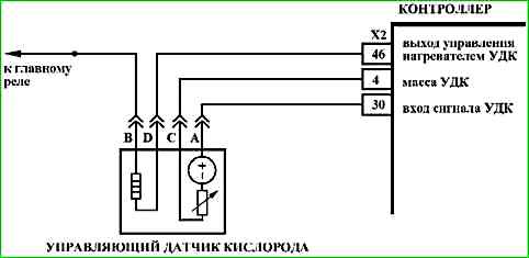
The sequence corresponds to the numbers on the map.
- 1 The conformity of the neutralizer type is checked.
- 2 The neutralizer is checked for damage.
- 3 The presence of faults in the exhaust system is checked.
Diagnostic information
The controller monitors the condition of the neutralizer by analyzing the signals of the control and diagnostic oxygen sensors installed before and after the neutralizer. If the neutralizer is working effectively, the value of the ANKAT parameter displayed by the diagnostic tool will tend to 0. The more the neutralizer degrades, the higher the ANKAT value.
The controller performs a neutralizer diagnostic cycle if:
- - the coolant temperature is not less than 70 °C;
- - the air temperature at the inlet is not lower than -10 °C;
- - the engine crankshaft speed is within 1800 ... 2500 rpm;
- - the engine load (parameter RL) has a stable value within 15 ... 50%.
Fulfillment of these conditions ensures that the neutralizer is sufficiently warmed up, and the controller can perform a diagnostic cycle.
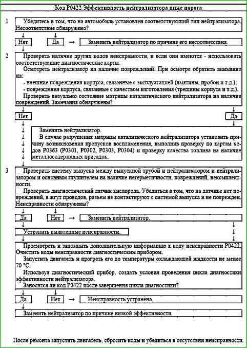
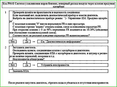
Code P0441 Evaporative emission system, air flow through the canister purge valve incorrect
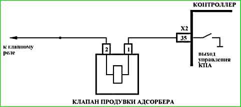
Code P0441 is recorded if:
- - the engine runs for more than 1200 seconds;
- - the engine is idling;
- - the control system check of the purge valve of the adsorber gave a negative result.
The malfunction indicator lights up on the 3rd trip after the occurrence of a persistent malfunction.
Description of tests
The sequence corresponds to the numbers on the map.
- 1 The presence of a permanent malfunction is checked.
- 2 The serviceability of the purge valve of the adsorber is checked.
Diagnostic information
The procedure for checking the purge valve of the adsorber is performed as follows:
- - at idle, the throughput of the purge valve of the adsorber changes smoothly from 0 to 92%;
- - the system monitors changes in the air-fuel mixture and the mass air flow rate.
If no changes are recorded, the purge valve or connecting hoses are faulty.
The test procedure is performed once per trip if the result is positive and twice if the first test result is negative.
The test can be interrupted if the engine is running unstably.
The following may be the cause of the fault code:
- - the purge valve of the adsorber is jammed in the open or closed state, which begins to open only at a high purge coefficient of the adsorber (above 70%);
- - pinching or clogging of the hoses connecting the adsorber to the engine;
- - incorrect connection of the hoses to the purge valve of the adsorber;
- - leak vacuum in the gasoline vapor recovery system.
Code P0444 Canister Purge Valve, Control Circuit Open
Code P0444 is set if:
- - engine is running;
- - self-diagnosis of the purge valve driver has determined that there is no load at the output.
The malfunction indicator lights up 2 drive cycles after the malfunction code has occurred.
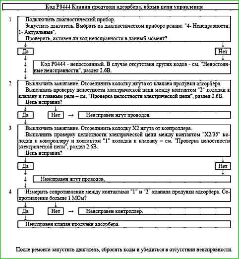
Description of tests
The sequence corresponds to the numbers on the map.
- 1 Checks for a permanent malfunction.
- 2 Checks the power supply circuit of the purge valve of the purge valve.
- 3 Checks the purge valve control circuit for an open.
- 4 Checks the serviceability of the purge solenoid valve canister.
Diagnostic information
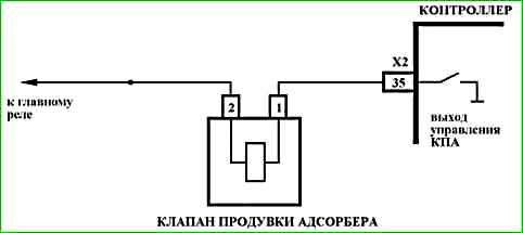
The controller uses a canister purge valve driver with a self-diagnostic function. It can detect faults such as an open circuit, short circuit to ground or power supply in the canister purge valve control circuit.
The valve status can be controlled using the diagnostic tool in the mode: "2 - IM Control".
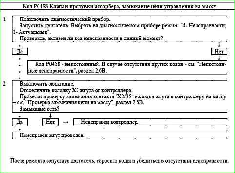
Code P0458 Purge valve canister, control circuit short to ground
Code P0458 is set if:
- - engine is running;
- - self-diagnosis of the canister purge valve driver has detected a short to ground at the output.
The malfunction indicator lights up 2 drive cycles after the malfunction code has occurred.
Description of tests
The sequence corresponds to numbers on the map.
- 1 Checks for a permanent fault.
- 2 Determines if there is a short to ground in the purge valve control circuit.
Diagnostic information
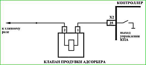
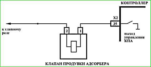
The ME17.9.71 controller uses a purge valve driver that has a self-diagnostic function. It can detect faults such as open, short to ground or short to power in the EVAP purge valve control circuit.
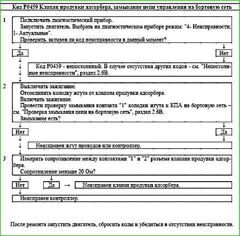
Code P0459 Evaporative Canister Purge Valve, Control Circuit Short to Battery
Code P0459 is set if:
- - the engine is running;
- - self-diagnosis of the purge valve driver has detected a short to power at the output.
The malfunction indicator lights up 2 drive cycles after the malfunction code has occurred.
Description of tests
The sequence corresponds to the numbers on the map.
- 1 The presence of a permanent malfunction is checked.
- 2 The presence of a short to power in the purge valve control circuit is determined.
- 3 The serviceability of the purge solenoid valve is checked adsorber.
Diagnostic information
The ME17.9.71 controller uses a canister purge valve driver with a self-diagnostic function. It can detect faults such as open, short to ground or short to power in the purge valve control circuit.
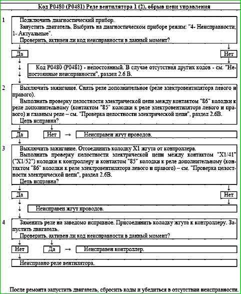
Code P0480 (P0481) Fan relay 1 (2), open control circuit
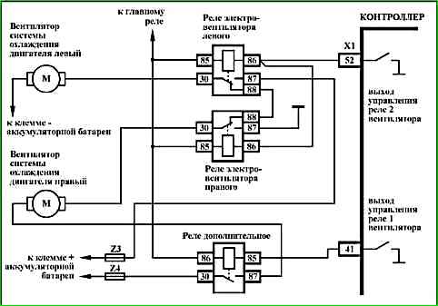
Code P0480 (P0481) is set if:
- - the engine is running;
- - the fan relay driver self-diagnosis has determined output no load.
The fault indicator lights up 2 drive cycles after the fault code has occurred.
Description of checks
The sequence corresponds to the numbers on the card.
- 1 The presence of a permanent fault is checked.
- 2 The fan relay power supply circuit is checked.
- 3 The fan relay control circuit is checked for an open circuit.
- 4 The fan relay is checked for serviceability.
Diagnostic information
The controller uses a fan relay driver with a self-diagnostic function. It can detect faults such as open, short to ground or short to power in the relay control circuit.
A short to power in the control circuit can be detected when the controller issues a command to turn on the fan.
The fan motor can be turned on using the scan tool in mode "2 - IM Control; Fan".
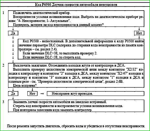
Code P0500 Vehicle speed sensor malfunction
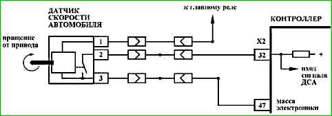
The P0500 code is set if:
- - engine speed NMOT is more than 1700 rpm;
- - the value of the load parameter RL is more than 50%;
- - coolant temperature TMOT is above 20 °C;
- - vehicle speed signal VFZG is less than 5 km/h.
The malfunction indicator lights up on 3rd trip after occurrence of persistent malfunction.
Description of tests
The sequence corresponds to the numbers on the map.
- 1 It is checked whether the code P0500 is active at the time of the request.
- 2 The electrical circuits are checked.
- 3 The faulty part is determined.
Diagnostic information
The diagnostic tool in the mode "1 - Parameters; 1 - General view" shows the vehicle speed "VFZG, km / h".
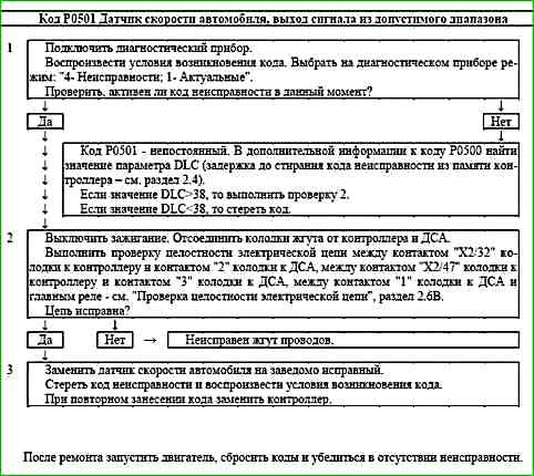
Code P0501 Vehicle speed sensor, signal out of acceptable range
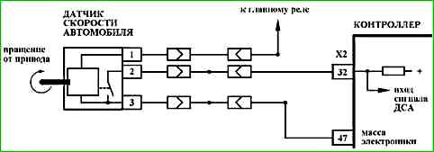
Code P0501 is set if the vehicle speed does not match the engine speed and gear for 3 seconds.
The malfunction indicator lamp comes on on the 3rd trip after a persistent malfunction has occurred.
Description of tests
The sequence corresponds to the numbers on the chart.
- 1 Checks if code P0501 is active at the time of the request.
- 2 Performs a test of the electrical circuits.
- 3 Determines the faulty part.
Diagnostic information
The scan tool is in mode "1 - Parameters; 1 - General view" shows the vehicle speed "VFZG, km / h".
Code P0504 Brake pedal switches "A/B", signal mismatch
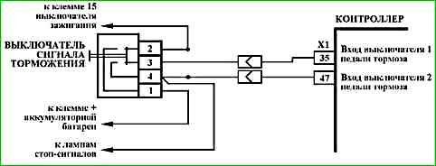
Code P0504 is set if:
- - signals from limit switches "1-4/2-3" of the brake pedal are out of alignment for more than 200 seconds with the engine running in idle mode;
- - or the number of presses on the brake pedal, determined by the signals from two limit switches "1-4/2-3" differs by the value of the diagnostic threshold on a moving vehicle.
The malfunction indicator lights up on the 3rd trip after the occurrence of a stable malfunction.
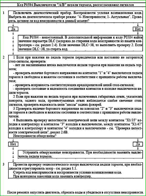
Description of tests
The sequence corresponds to the numbers on the map.
- 1 Checked, is the P0504 code active at the time of the request.
- 2 Electrical circuits are checked.
- 3 Perform brake pedal switch gap adjustment.
Diagnostic information
The diagnostic tool in the "1 - Parameters; 1 - General view" mode shows the B_BREMS status bit of contacts "2-3" of the brake pedal switch and the B_BREMSS status bit of contacts "1-4" of the brake pedal switch.
It is also possible to check the status of contacts "1-4" using the brake light bulbs.
If a signal mismatch is detected, switches "1-4/2-3" the engine management system will operate in emergency mode until the end of the current trip.
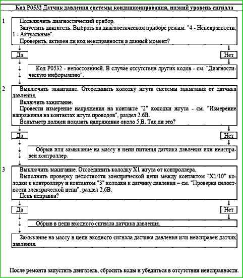
Code P0532 Air Conditioning Pressure Sensor, Low Input

Code P0532 is set if:
- - engine running;
- - pressure sensor signal voltage is less than 0.2 V.
When this code occurs, the malfunction indicator does not light.
Description of tests
The sequence corresponds to the numbers on the map.
- 1 Checks for a permanent fault.
- 2 Checks for supply voltage.
- 3 Checks for proper operation of the input signal circuit.
Diagnostic information
An intermittent fault may be caused by poor contact, damaged insulation or core wires.
Make sure that the following faults are absent.
Loss of connection of the "X1/10" contact of the ignition system harness connector and the controller.
Inspect the harness connector and the controller connector for completeness and correctness of articulation, damage to the locks, presence of damaged contacts and quality of connection of contacts with the wire.
Harness damage. Check the harness for damage. If the harness appears normal, move the corresponding connector and harness while monitoring the diagnostic tool.
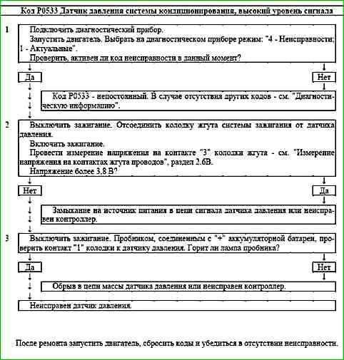
Code P0533 Air Conditioning Pressure Sensor, High Input

Code P0533 is stored if:
- - the engine is running;
- - the pressure sensor signal voltage is more than 3.8 V.
When this code occurs, the malfunction indicator does not light.
Description of tests
The sequence corresponds to the numbers on the map.
- 1 Checks for a permanent malfunction.
- 2 Checks for voltage at terminal "3" of the harness connector to the pressure sensor.
- 3 Checks for proper operation of the sensor ground circuit.
Diagnostic information
Malfunction intermittent nature may be caused by poor contact, damage to the insulation or core of the wire.
It is necessary to make sure that the following faults are absent.
Unreliable connection of the contact "X1/3" of the ignition system harness block and the controller.
Inspect the harness block and the controller connector for completeness and correctness of articulation, damage to the locks, the presence of damaged contacts and the quality of the connection of the contacts with the wire.
Damage to the harness. Check the harness for damage.
If the harness is outwardly normal, move the corresponding connector and harness, while observing the readings of the diagnostic tool.
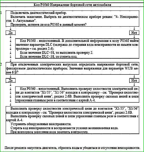
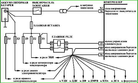
Code P0560 Vehicle on-board network voltage
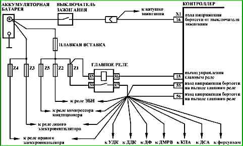
Code P0560 is entered if:
- voltage at contacts "X1/55", "X1/56" of the controller is below the controller operability threshold (below 6 V).
The malfunction indicator lights up 5 seconds after the malfunction code occurs.
Description of checks
The sequence corresponds to the numbers on the map.
- 1 It is checked whether the code is currently active.
- 2 Perform a check of the on-board network voltage using the diagnostic device.
Diagnostic information
The diagnostic device in the mode "1 - Parameters; 1 - General view" shows the on-board network voltage "UBSQ, B", measured at the contact "Х1/16".
In the mode "1 - Parameters; 6 - Additional Parameters; 3 - ADC Inputs" shows the on-board network voltage "WUB, B", measured at the contacts "Х1/55", "X1/56".
If there is a persistent malfunction, the engine management system will go into emergency mode for the current trip.
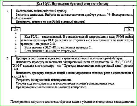
Code P0561 On-board network voltage is unstable
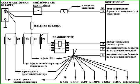
Code P0560 is recorded if:
- - instantaneous voltage changes at contacts "X1/55", "X1/56" of the controller are above the threshold value;
- - the engine is running.
The malfunction indicator lights up 5 seconds after the malfunction code has occurred.
Description of tests
The sequence corresponds to the numbers on the map.
- 1 It is checked whether the code is currently active.
- 2 It is checked that the terminals are securely fastened to the battery.
Diagnostic information
The diagnostic device in the mode "1 - Parameters; 1 - General view" shows the on-board network voltage "UBSQ, V", measured at the contact "X1/16".
In the mode "1 - Parameters; 6 - Additional Parameters; 3 - ADC inputs" shows the on-board voltage "WUB, B", measured at the contacts "X1/55", "X1/56".
If there is a persistent malfunction, the engine management system will go into emergency mode during the current trip.
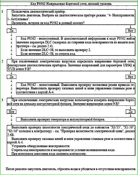
Code P0562 On-board voltage, low level
Code P0562 is entered if:
- - voltage at contacts "X1/55", "X1/56" of the controller is below 9 V;
- - the engine is running.
The malfunction indicator lights up 5 seconds after the malfunction code has occurred.
Description of checks
The sequence corresponds to the numbers on the map.
- 1 It is checked whether the code is currently active.
- 2 Perform a check of the on-board network voltage using diagnostic tool.
- 3 Perform a check of the on-board network voltage at the battery terminals.
Diagnostic information
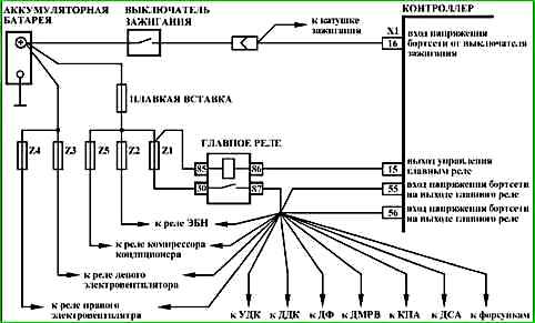
The diagnostic tool in the "1 - Parameters; 1 - General view" mode shows the on-board network voltage "UBSQ, B" measured at the "X1/16" contact.
In the "1 - Parameters; 6 - Additional Parameters; 3 - ADC inputs" shows the on-board voltage "WUB, B", measured at the contacts "X1/55", "X1/56".
If there is a persistent malfunction, the engine management system will go into emergency mode during the current trip.
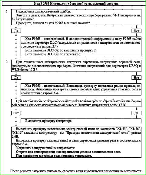
Code P0563 On-board voltage, high level
Code P0563 is entered if:
- - voltage at contacts "X1/55", "X1/56" of the controller is more than 17 V;
- - the engine is running.
The malfunction indicator lights up 5 seconds after the malfunction code has occurred.
Description of checks
The sequence corresponds to the numbers on the map.
- 1 It is checked whether the code is currently active.
- 2 Perform a check of the on-board network voltage using diagnostic tool.
- 3 Perform a check of the on-board network voltage at the battery terminals.
Diagnostic information
The diagnostic tool in the "1 - Parameters; 1 - General view" mode shows the on-board network voltage "UBSQ, B" measured at the "X1/16" contact.
In the "1 - Parameters; 6 - Additional Parameters; 3 - ADC inputs" shows the voltage of the on-board network "WUB, B", measured at the contacts "X1/55", "X1/56".
If there is a persistent malfunction, the engine management system will go into emergency mode during the current trip.
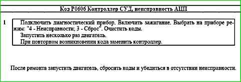
Code P0606 ECU controller, ADC malfunction
Code P0606 is recorded if:
- - ignition is on;
- - internal tests of the controller have determined an ADC malfunction.
The malfunction indicator lights up 5 s after the malfunction code has occurred.
Description of tests
The sequence corresponds to the numbers on the map.
1 If the malfunction is recorded periodically, it is necessary to replace the controller.
Diagnostic information
From the moment the ignition is turned on until the moment the main relay is disconnected, the controller performs internal tests aimed at determining the equipment malfunction. processor.
Some of the tests are performed once when the ignition is turned on and off.
Some of the tests are performed cyclically.
When a malfunction is detected, the processor is reset and initialized.
If the controller is replaced, it is necessary to perform the throttle valve zero adaptation procedure and the misfire diagnostic function adaptation procedure.
Code P0615 Additional starter relay, open circuit control
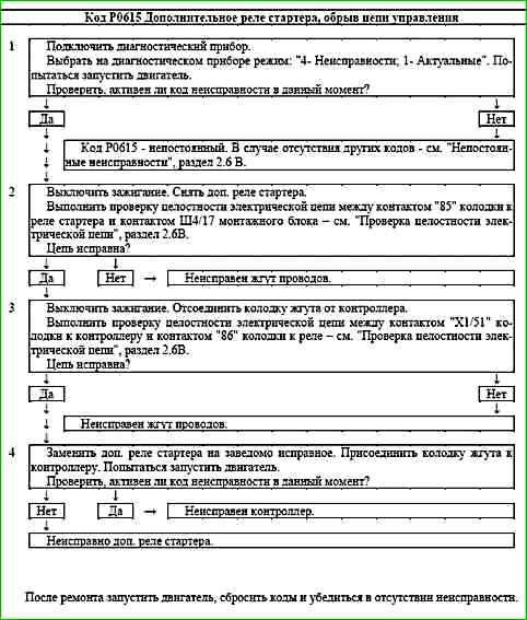
Code P0615 is entered if:
- - engine running;
- - add. driver self-diagnosis. The starter relay has detected a fault.
When this code occurs, the fault indicator does not light.
Description of tests
The sequence corresponds to the numbers on the map.
- 1 Checks for a permanent fault.
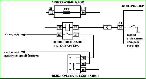
- 2 Checks the power supply circuit of the additional starter relay.
- 3 Checks the control circuit of the additional starter relay for an open circuit.
- 4 Checks the serviceability of the additional starter relay.
Diagnostic information
The controller uses a driver for the additional starter relay, which has a self-diagnostic function. It can detect faults such as open circuit, short circuit to ground or power supply of the relay control circuit.
The code may be caused by incorrect connection of the alarm.
Control the inclusion of additional. starter relay can be done using the diagnostic tool in the "2 - IM control; Starter relay" mode.
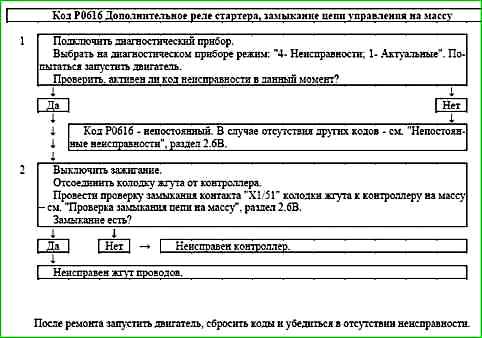
Code P0616 Additional starter relay, control circuit short to ground
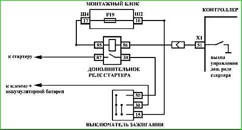
Code P616 is set if:
- - the engine is running;
- - self-diagnosis of the starter auxiliary relay driver has detected a short circuit to ground at the output.
When this code occurs, the malfunction indicator does not light.
Description of tests
The sequence corresponds to the numbers on the map.
- 1 The presence of a permanent fault is checked.
- 2 The presence of a short circuit to ground in the starter auxiliary relay control circuit is determined.
Diagnostic information
The controller uses a starter auxiliary relay driver with a self-diagnostic function. It can detect faults such as open circuit, short circuit to ground or power supply of the relay control circuit.
The code may be caused by incorrect connection of the alarm.
Control the inclusion of additional. starter relay can be done using the diagnostic tool in the "2 - IM control; Starter relay" mode.
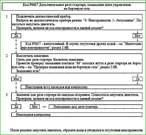
Code P0617 Additional starter relay, control circuit short to battery
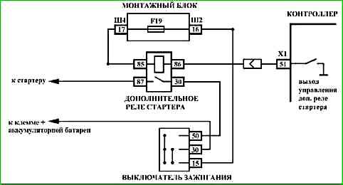
Code P0617 is entered if:
- - the engine is running;
- - self-diagnosis of the driver of the additional relay of the starter has determined a short circuit on the power source at the output th.
When this code occurs, the malfunction indicator does not light.
Description of tests
The sequence corresponds to the numbers on the map.
- 1 The presence of a permanent fault is checked.
- 2 The presence of a short circuit to the power source of the control circuit of the additional starter relay is determined.
- 3 The serviceability of the additional starter relay is checked.
Diagnostic information
The controller uses a driver for the additional starter relay, which has a self-diagnostic function. It can detect the presence of such faults as an open circuit, short circuit to ground or power source of the relay control circuit.
The code may be caused by an incorrect connection of the alarm system.
Control the inclusion of additional. starter relay can be done using the diagnostic tool in the "2 - IM control; Starter relay" mode.
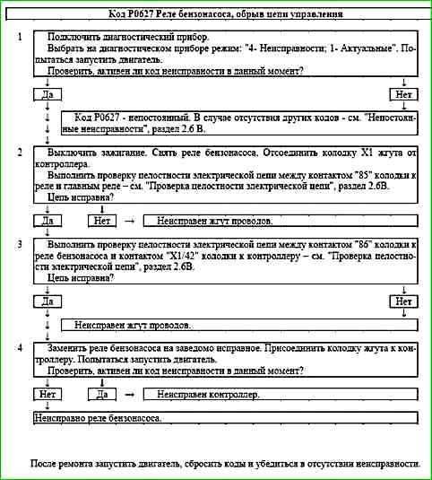
Code P0627 Fuel pump relay, open control circuit
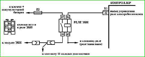
Code P0627 is set if:
- - the engine is running;
- - self-diagnosis of the fuel pump relay driver has detected a malfunction.
When this code occurs, the malfunction indicator does not light.
Description of tests
The sequence corresponds to the numbers on the map.
- 1 Checks for a permanent malfunction.
- 2 Checks the power supply circuit of the fuel pump relay.
- 3 Checks the control circuit of the fuel pump relay for an open.
- 4 Checks the serviceability of the relay fuel pump.
Diagnostic information
The controller uses a fuel pump relay driver with a self-diagnostic function. It can detect faults such as open, short to ground or short to power supply of the relay control circuit.
The fuel pump relay can be controlled using the diagnostic tool in the "2 - IM Control" mode.
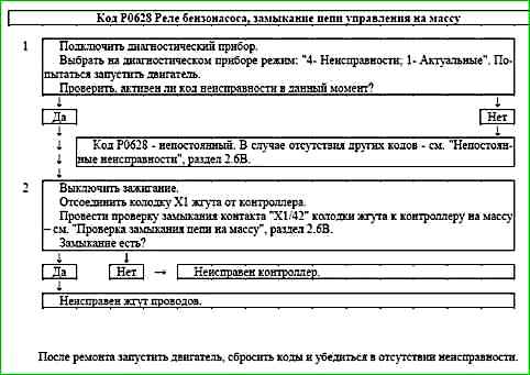
Code P0628 Fuel pump relay, control circuit short to ground
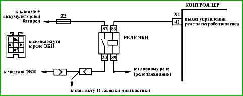
Code P628 is entered if:
- - the engine is running;
- - self-diagnosis of the fuel pump relay driver has detected a short circuit to ground at the output.
When this code occurs, the malfunction indicator does not light.
Description of tests
The sequence corresponds to the numbers on the map.
- 1 The presence of a permanent malfunction is checked.
- 2 The presence of a short circuit to ground in the relay control circuit is determined fuel pump.
Diagnostic information
The controller uses a fuel pump relay driver with a self-diagnostic function. It can detect faults such as open, short to ground or short to power supply in the relay control circuit.
The fuel pump relay can be controlled using the diagnostic tool in the "2 - IM Control" mode.
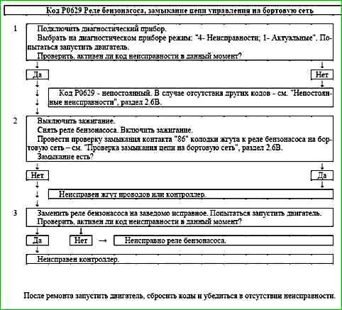
Code P0629 Fuel pump relay, control circuit short to battery
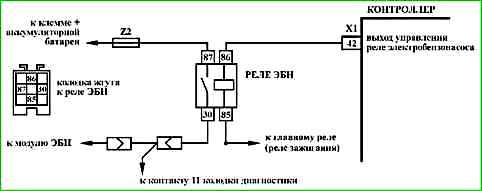
Code P0629 is entered if:
- - the engine is running;
- - self-diagnosis of the fuel pump relay driver has detected a short circuit to the power source at the output.
When this code occurs, the malfunction indicator does not light.
Description of tests
The sequence corresponds to the numbers on the map.
- 1 The presence of a permanent malfunction is checked.
- 2 The presence of a short circuit to the power source of the fuel pump relay control circuit is determined.
- 3 The fuel pump relay is checked for proper operation.
Diagnostic information
The controller uses a fuel pump relay driver, o having a self-diagnostic function. It can detect faults such as open, short to ground or short to power supply in the relay control circuit.
The fuel pump relay can be controlled using the diagnostic tool in the "2 - IM Control" mode.
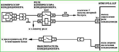
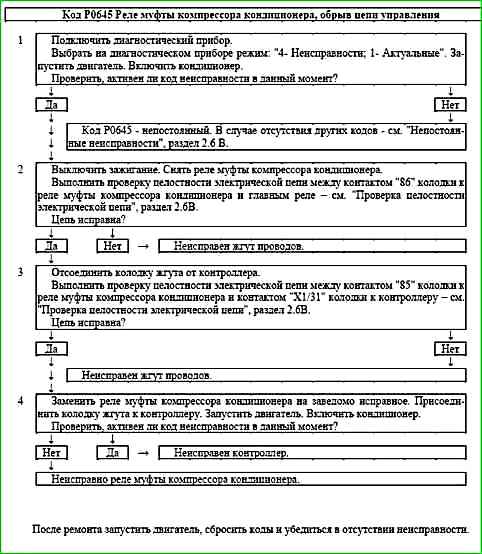
Code P0645 Air conditioning compressor clutch relay, open control circuit
Code P0645 is entered if:
- - the engine is running;
- - the command to turn on the air conditioner is executed (B_KOE = ON);
- - self-diagnosis of the air conditioner compressor clutch relay driver has detected a malfunction.
The malfunction indicator lights up 2 drive cycles after the malfunction code has occurred.
Description of checks
The sequence corresponds to the numbers on the map.
- 1 The presence of a constant malfunctions.
- 2 The power supply circuit of the air conditioner compressor clutch relay is checked.
- 3 The control circuit of the air conditioner compressor clutch relay is checked for an open circuit.
- 4 The serviceability of the air conditioner compressor clutch relay is checked.
Diagnostic information
The controller uses a driver for the air conditioner compressor clutch relay, which has a self-diagnostic function. It can detect faults such as open, short to ground or short to power supply in the relay control circuit.
The activation of the air conditioning compressor clutch starter can be controlled using the diagnostic tool in the "2 - IM Control" mode.
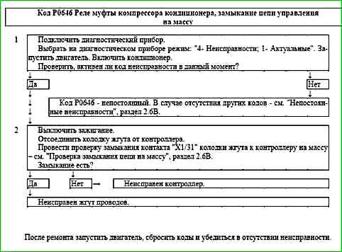
Code P0646 Air conditioning compressor clutch relay, control circuit short to ground
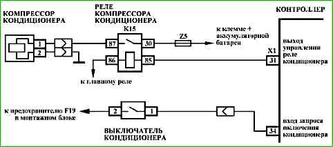
Code P646 is entered if:
- - the engine is running;
- - the command to turn on the air conditioner is executed (B_KOE = ON);
- - self-diagnosis of the air conditioner compressor clutch relay driver has detected a short circuit to ground at the output.
The malfunction indicator lights up 2 drive cycles after the occurrence of the malfunction code.
Description of checks
The sequence corresponds to the numbers on the map.
- 1 The presence of a constant malfunctions.
- 2 The presence of a short circuit to ground in the control circuit of the air conditioner compressor clutch relay is determined.
Diagnostic information
The controller uses a driver for the air conditioner compressor clutch relay, which has a self-diagnostic function. It can detect faults such as open, short to ground or short to power supply in the relay control circuit.
The A/C compressor clutch relay can be controlled using the diagnostic tool in the "2 - IM Control" mode.
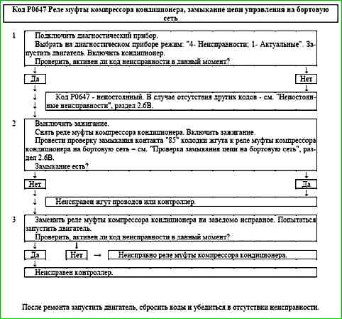
Code P0647 A/C compressor clutch relay, control circuit short to battery
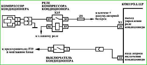
Code P0647 is entered if:
- - the engine is running;
- - the command to turn on the air conditioner is executed (B_KOE = ON);
- - self-diagnosis of the air conditioner compressor clutch relay driver has detected a short circuit to the power source at the output.
The malfunction indicator lights up 2 drive cycles after the occurrence of the malfunction code.
Description of tests
The sequence corresponds to the numbers on map.
- 1 Checks for a permanent fault.
- 2 Determines if there is a short to power in the air conditioner compressor clutch relay control circuit.
- 3 Checks for proper operation of the air conditioner compressor clutch relay.
Diagnostic information
The controller uses a driver for the clutch relay to compressor, which has a self-diagnosis function. It can detect faults such as an open circuit, short circuit to ground or power supply of the relay control circuit.
The activation of the air conditioning compressor clutch relay can be controlled using the diagnostic tool in the "2 - IM Control" mode.
Code P0691 (P0693) Fan relay 1 (2), control circuit short to ground
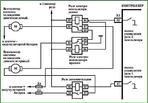
Code P0691 (P0693) is entered if:
- - the engine is running;
- - self-diagnosis of the fan relay driver has detected a short to ground at the output.
The malfunction indicator lights up 2 drive cycles after the malfunction code has occurred.
Description of tests
The sequence corresponds to the numbers on the map.
- 1 Checks for a permanent fault.
- 2 Determines if there is a short to ground in the fan relay control circuit.
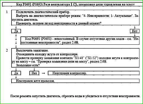
Diagnostic information
The controller uses a fan relay driver with a self-diagnostic function. It can detect faults such as open, short to ground or short to power in the relay control circuit.
A short to power in the control circuit can be detected when the controller issues a command to turn on the fan.
The fan motor can be turned on using the diagnostic tool in mode "2 - IM control; Fan".
Code P0692 (P0694) Fan relay 1 (2), short to power in the control circuit
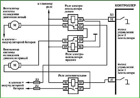
Code P0692 (P0694) is recorded if:
- - the engine is running;
- - self-diagnosis of the fan relay driver has detected a short circuit to the power source at the output.
The malfunction indicator lights up 2 drive cycles after the malfunction code has occurred.
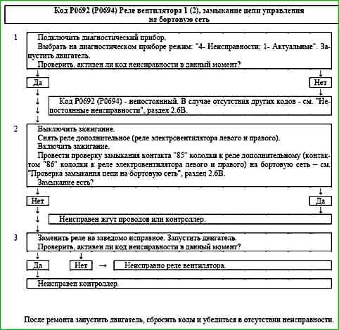
Description of tests
The sequence corresponds to the numbers on the map.
- 1 The presence of a permanent malfunction is checked.
- 2 The presence of a short circuit to the power source of the fan relay control circuit is determined.
- 3 The serviceability of the fan relay is checked.
Diagnostic information
The controller uses a fan relay driver with a self-diagnostic function. It can detect faults such as open, short to ground or short to power in the relay control circuit.
A short to power in the control circuit can be detected when the controller issues a command to turn on the fan.
The fan motor can be turned on using the scan tool in mode "2 - IM Control; Fan".
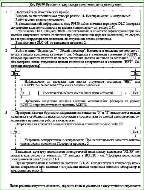
Code P0830 Clutch Pedal Switch, Circuit faulty
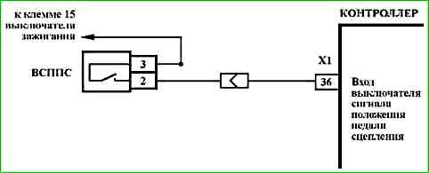
Code P0830 is entered if:
- - the engine is running;
- - the speed sensor error is not active;
- - the vehicle is moving;
- - there is no change in the signal voltage at the "X1/36" input of the controller when the clutch pedal is pressed / released during gear shifting.
The malfunction indicator lights up in 3rd trip after a persistent malfunction has occurred.
Description of tests
The sequence corresponds to the numbers on the map.
- 1 The presence of the P0830 code in the ECU memory is checked.
- 2 The operation of the clutch pedal switch (CPS) is checked.
- 3 The electrical circuits are checked.
Diagnostic information
When the clutch pedal is pressed, the switch ь open.
The scan tool in mode "1 - Parameters; 1 - General view" shows the B_KUPPL status bit of the clutch pedal switch.
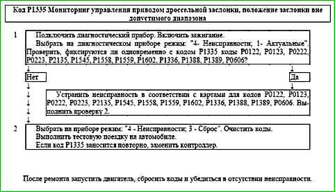
Code P1335 Throttle Actuator Control Monitoring, Throttle Position Out of Range
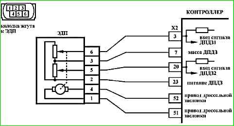
Code P1335 is entered if:
- - ignition is on;
- - throttle position exceeds maximum permissible for 0.5 s;
- - throttle position is in maximum permissible position for 3 s.
The malfunction indicator lights up 5 s after the malfunction code has occurred.
Description of tests
The sequence corresponds to the numbers on the map.
- 1 Using a diagnostic tool The presence of codes P0122, P0123, P0222, P0223, P2135, P1545, P1558, P1559, P1602, P1336, P1388, P1389, P0606 is checked. Troubleshooting should begin with these codes.
- 2 If the malfunction is recorded periodically, the controller must be replaced.
Diagnostic information
From the moment the ignition is turned on until the moment the main relay is disconnected, the controller monitors the throttle position. The maximum permissible throttle position is calculated depending on engine speed, accelerator pedal position, engine temperature, etc.
If a malfunction is detected, the engine management system will operate in emergency mode until the end of the current trip:
- de-energizing the throttle actuator and limiting the engine speed (2500 rpm).
The reason for recording the P1335 code may be a malfunction of the processor hardware or software errors leading to incorrect calculation of the specified throttle position.
Code P1336 Throttle actuator control monitoring, mismatch of signals of sensors "A" / "B" of the throttle position
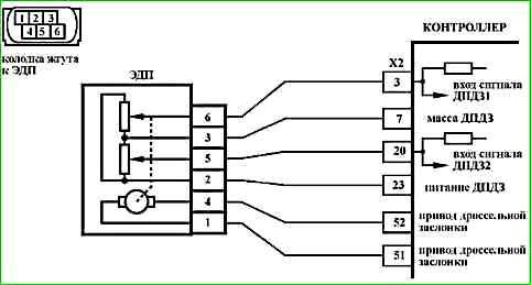
Code P1336 is stored if:
- - ignition is on;
- - sum of signals of TPS A and TPS V differs from the reference voltage of 5 V by more than 0.3 V for 0.5 s.
The malfunction indicator lights up 5 s after the malfunction code has occurred.
Description of tests
The sequence corresponds to the numbers on the map.
- 1 Using the diagnostic tool, it is checked whether the code P1336 is active at the time of diagnostics.
- 2 A check is performed in accordance with the map for the code P2135.
Diagnostic information
The diagnostic tool is in the mode "1 - Parameters; 6 - Additional Parameters; 3 - ADC inputs" shows the signals of TPS A (UDKP1) and TPS B (UDKP2) in volts.
When the throttle valve is opened, the signal of TPS A increases, the signal of TPS B decreases.
When the throttle valve is fully closed, the signal of TPS A should be in the range of 0.3 ... 0.6 V, the signal of TPS B should be in the range of 4.4 ... 4.7 V.
The controller recalculates the volt signals of TPS A and TPS B into a percentage of throttle opening.
The diagnostic tool is in the mode "1 - Parameters; 1 - General view" displays the percentage of throttle valve opening WDKBA, which is calculated as the arithmetic mean of the signals of TPS A (%) and TPS B (%). 0% corresponds to a fully closed throttle valve. 100% corresponds to the maximum opening of the throttle valve.
The signals of TPS A and TPS B are mismatched if the following condition is met:
|5 V – (UDKP1 + UDKP2)| > 0.3 V.
If a mismatch of the signals of TPS A and TPS B is detected, the engine management system will operate in emergency mode until the end of the current trip:
- de-energization of the throttle actuator and limitation of engine speed (2500 rpm).
In case of replacement of the ECM or ECM controller, or resetting the controller using a diagnostic device (mode "5 - Additional tests; 1 - ECU reset with initialization"), it is necessary to perform the throttle valve zero adaptation procedure.
To do this, and when the vehicle is stationary, turn on the ignition, wait 30 seconds, turn off the ignition, wait for the main relay to disconnect.
Adaptation will be interrupted if:
- - the engine is cranking;
- - the vehicle is moving;
- - the accelerator pedal is pressed;
- - the engine temperature is below 5 °C or above 100 °C;
- - the ambient air temperature is below 5 °C.
If the throttle actuator is de-energized, the throttle valve is held in the Limp home position (7-8%) by means of the direct and return springs.
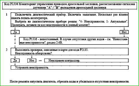
Code P1388 Throttle Actuator Control Monitoring, Accelerator Pedal Position Sensor "A"/"B" Signal Mismatch
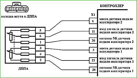
Code P1388 is set if:
- - ignition is on;
- - signal from accelerator pedal position sensor A (UPWG1ROH) and double signal from accelerator pedal position sensor B (2 × UPWG2ROH) differ by the threshold value for 0.5 s.
The malfunction indicator lights up 5 s after the malfunction code has occurred.
Description of tests
The sequence corresponds to the numbers on the map.
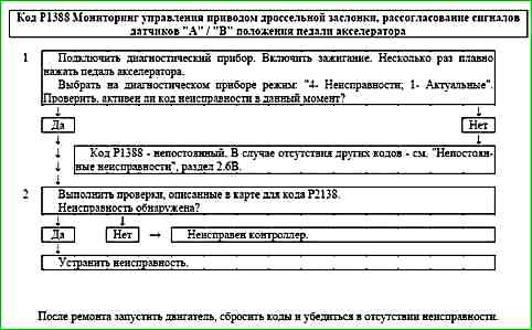
- 1 Using the diagnostic tool, it is checked whether the P1388 code is active at the time of diagnosis.
- 2 A check is performed in accordance with the map for code P2138.
Diagnostic information
If a mismatch between the signals of the DPPA A and DPPA B is detected, the engine management system will operate in emergency mode until the end of the current trip:
- de-energization of the electric throttle drive and limitation of engine speed (2500 rpm).
The diagnostic device in mode "1 - Parameters; 6 - Additional Parameters; 3 - ADC inputs" shows the signals of DPPA A (UPWG1ROH) and DPPA B (UPWG2ROH) in volts.
The signals of DPPA A and DPPA B increase proportionally to the pressing of the accelerator pedal. At any position of the accelerator pedal, the signal of DPPA A should be twice as large as the signal of DPPA B.
When the accelerator pedal is released, the signal of DPPA A should be in the range of 0.46 ... 0.76 V, the signal of DPPA B should be in the range of 0.23 ... 0.38 V.
To calculate the accelerator pedal position, expressed as a percentage (WPED), the minimum signal from UPWG1ROH and 2 × UPWG2ROH is used.
Each time the ignition is turned on, the controller determines the zero position of the accelerator pedal. The position 100% is achieved at a voltage of 2.30 V / 1.15 V from the DPPA A / DPPA B sensor.
Code P1389 Throttle actuator control monitoring, engine speed out of acceptable range
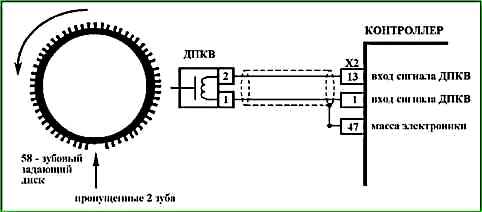
Code P1389 is entered if:
- - the engine is running;
- - the engine speed calculated by different methods differs by more than 300 rpm for 0.3 s.
The malfunction indicator lights up 5 s after the malfunction code has occurred.
Description of tests
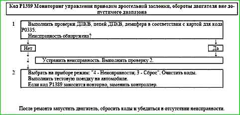
The sequence corresponds to the numbers on the map.
- 1 The crankshaft position sensor and damper are checked in accordance with the map for the code P0335.
- 2 If the fault is recorded periodically, the controller must be replaced.
Diagnostic information
Engine speed is calculated based on the CKP sensor signal. To improve reliability, engine speed calculation is performed using two different methods. In this case, the controller constantly monitors the discrepancy between the values obtained by two different methods.
If the discrepancy exceeds 300 rpm for 0.3 s, the engine management system will operate in emergency mode until the end of the current trip:
- de-energizing the throttle actuator and limiting the engine speed (2500 rpm).
The reason for recording the P1389 code may be a malfunction of the crankshaft position sensor circuit (signal loss, screen damage, etc.).
Code P1390 Throttle actuator control monitoring, incorrect response to a system malfunction
Code P1390 is recorded if:
- - the engine is running;
- - incorrect engine response to the speed limit request from the monitoring function.
The malfunction indicator lights up 5 s after the malfunction code has occurred.
Description of tests
The sequence corresponds to the numbers on the map.
1 If the malfunction is recorded periodically, it is necessary to replace the controller.
Diagnostic information
If any malfunction of the throttle actuator is detected (mechanical malfunction, malfunction of electrical circuits), the engine management system will operate in emergency mode until the end of the current trip:
- de-energization of the throttle actuator and limitation of engine speed (2500 rpm).
On-board diagnostics monitors the engine behavior in emergency mode.

Code P1391 Throttle actuator control monitoring, no response to a malfunction in the system
Code P1391 is recorded, if:
- - the engine is running;
- - there is no engine response to the request for speed limitation from the monitoring function.
The malfunction indicator lights up 5 s after the malfunction code has occurred.
Description of checks
The sequence corresponds to the numbers on the map.
1 If the malfunction is recorded periodically, the controller must be replaced.
Diagnostic information
If any malfunction of the electric throttle valve drive is detected (mechanical malfunction, malfunction of electrical circuits), the engine management system will operate in emergency mode until the end of the current trip:
- de-energization of the electric throttle valve drive and limitation of engine speed (2500 rpm).
On-board diagnostics monitors the behavior of the engine in emergency mode. mode.

Code P1545 Throttle Actuator, Throttle Position Out of Range
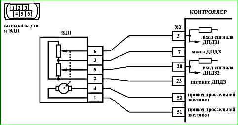
Code P1545 is set if:
- - ignition is on;
- - actual throttle position differs from the set value by the threshold value for 0.5 s.
or
- PID controller values exceed the threshold value for 5 s.
The malfunction indicator lights up 5 s after the malfunction code has occurred.
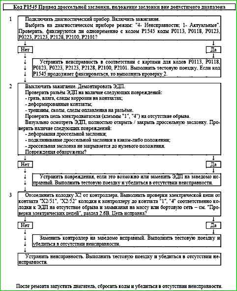
Description of tests
The sequence corresponds to the numbers on the map.
- 1 Using the diagnostic tool, check whether codes P0113, P0118, P0123, P0223, are recorded simultaneously with code P1545, P2123, P2128, P2100, P2101. If they are recorded, then the troubleshooting should begin with these codes.
- 2 The mechanical and electrical components of the throttle body are checked.
- 3 The throttle actuator control circuits are checked.
Diagnostic information
If a P1545 fault is detected, the engine management system will operate in emergency mode until the end of the current trip:
- de-energization of the throttle actuator and limitation of engine speed (up to 3500 rpm depending on the accelerator pedal position).
The diagnostic tool in the mode "1 - Parameters; 1 - General view" displays the percentage of opening of the WDKBA throttle valve.
In case of replacement of the ECM or ECM controller, or reset of the controller using the diagnostic tool (mode "5 – Additional tests; 1 - ECU reset with initialization"), it is necessary to perform the throttle valve zero adaptation procedure.
To do this, turn on the ignition with the vehicle stationary, wait 30 seconds, turn off the ignition, wait for the main relay to disconnect.
Adaptation will be interrupted if:
- - the engine is cranking;
- - the vehicle is moving;
- - the accelerator pedal is pressed;
- - the engine temperature is below 5 °C or above 100 °C;
- - the ambient air temperature is below 5 °C.
If the throttle valve electric drive is de-energized, the throttle valve is held in the Limp position by means of the direct and return springs home (7-8%).
Code P1558 Throttle actuator, return spring malfunction
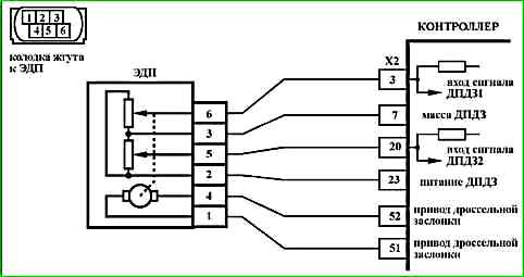
Code P1558 is set if:
- - ignition is on;
- - return spring test is performed with a negative result.
The malfunction indicator lights up 5 s after the malfunction code has been generated.
Description of tests
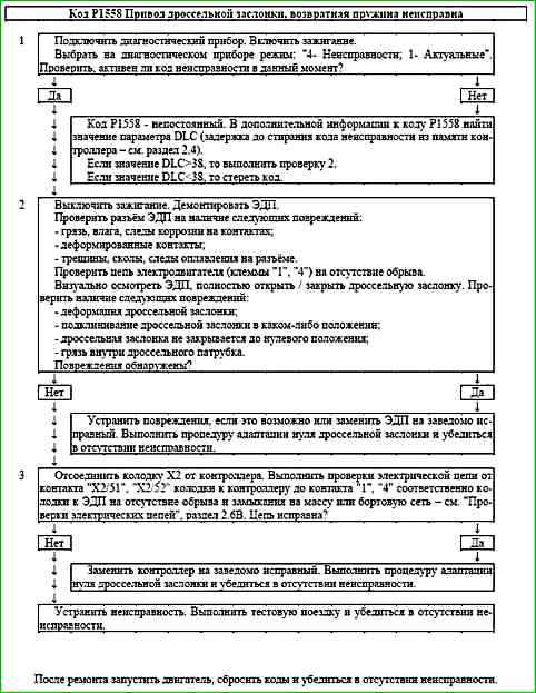
The sequence corresponds to the numbers on the map.
- 1 Using the scan tool, it is checked whether the P1558 code is active at the time of diagnostics.
- 2 A check of the mechanical and electrical components of the throttle body is performed.
- 3 A check of the throttle actuator control circuits is performed.
Diagnostic information
If fault P1558 is detected, the engine management system will operate in emergency mode until the end of the current trip:
- - the electric throttle drive is not de-energized, but the throttle valve is constantly in the Limp home position (7-8%);
- - engine speed limitation (up to 3500 rpm depending on the accelerator pedal position).
The diagnostic tool is in mode "1 - Parameters; 1 - General view" displays the percentage of the WDKBA throttle valve opening.
When the ignition is turned on, the controller performs:
- - return spring test;
- - check of the valve position with the electric drive de-energized;
- - adaptation of the zero position of the throttle valve;
- - direct spring test.
During the return spring test, the throttle valve opens to a specified value, after which the electric drive is de-energized. The controller records the time of the throttle valve return to the Limp home position. If the time exceeds the threshold value, the test is considered complete with a negative result.
Code P1559 Throttle Actuator, Valve Position at Rest Out of Range
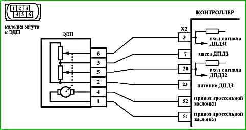
Code P1559 is recorded if:
- - ignition is on;
- - throttle position in de-energized state is outside the permissible range.
The malfunction indicator lights up 5 s after the malfunction code has occurred.
Description of checks
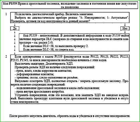
The sequence corresponds to the numbers on the map.
- 1 Using the diagnostic tool, it is checked whether the P1559 code is active at the time of diagnostics.
- 2 The mechanical and electrical components of the throttle pipe are checked.
Diagnostic information
If malfunction P1559 is detected, the engine management system will operate in normal mode.
The diagnostic tool in mode "1 - Parameters; 1 - General view" displays the percentage of opening of the WDKBA throttle valve.
When the ignition is turned on, the controller performs:
- - return spring test;
- - check of the valve position with the electric drive de-energized;
- - adaptation of the zero position of the throttle valve;
- - direct spring test.
Code P1564 Throttle actuator control system, zero position adaptation interrupted due to low battery voltage
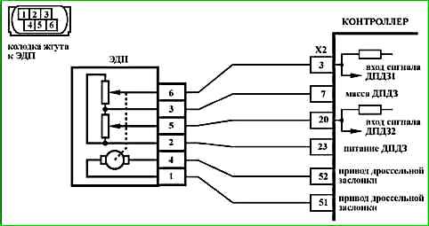
Code P1564 is stored if:
- - ignition is on;
- - throttle position zero position readaptation procedure interrupted due to incorrect battery voltage.
Malfunction indicator lights up 5 seconds after the occurrence of the fault code.
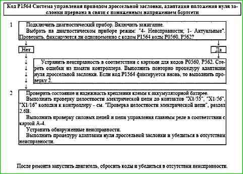
Description of checks
Sequence ь corresponds to the numbers on the map.
- 1 Using a diagnostic tool, check for codes P0560, P0562. If the codes are present, then the troubleshooting should begin with these codes.
- 2 The controller power supply circuits are being checked.
Diagnostic information
If the P1564 fault is detected, the engine management system will operate in the normal mode, the values obtained in the previous adaptation procedure will be used to calculate the throttle position.
The diagnostic tool in the "1 - Parameters; 1 - General view" mode displays the percentage of opening of the WDKBA throttle valve.
When the ignition is turned on, the controller performs:
- - return spring test;
- - check of the throttle position with the electric drive de-energized;
- - adaptation of the throttle position zero;
- - direct spring test.
If the controller new (the adaptation is carried out for the first time), then all the above procedures are performed immediately after turning on the ignition for 1.5 seconds.
If the controller was trained earlier, then immediately after turning on the ignition, a return spring test is performed. The remaining procedures will be performed within the next 30 seconds if none of the following conditions are violated during this time:
- - the engine is not cranking;
- - the vehicle is not moving;
- - the accelerator pedal is not pressed;
- - the engine temperature is above 5 °C and below 100 °C;
- - the ambient air temperature is above 5 °C.
If the throttle actuator is de-energized, the throttle valve is held in the Limp home position (7-8%) by means of the direct and return springs.
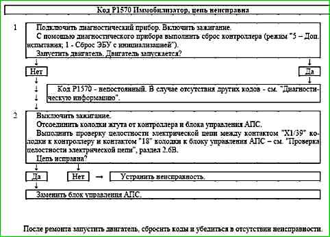
Code P1570 Immobilizer, circuit malfunction
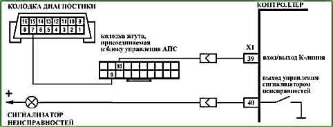
Code P1570 is entered if:
- - the controller and APS are "trained";
- - the controller does not receive a response from the control unit APS.
When this code occurs, the malfunction indicator does not light.
Description of tests
The sequence corresponds to the numbers on the map.
- 1 The presence of a permanent fault is checked.
- 2 The serviceability of the circuit between contact "18" of the APS control unit and contact "X1/39" of the controller is checked.
Diagnostic information
When the ignition is turned on, the controller sends a request to communicate with the APS. If the controller does not receive a response from the APS control unit or receives an unrecognized response, then the P1570 code is entered.
This code may be caused by an unreliable connection in the pads to the APS control unit and the controller.
It is necessary to check the connections for completeness and correctness of articulation, damage to the locks, the presence of damaged contacts and the quality of the connection of the contacts to the wire.
Code P1578 Throttle actuator control system, zero position adaptation value is out of acceptable range
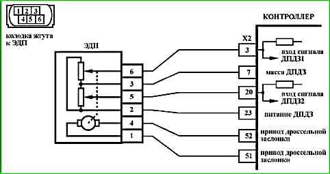
Code P1578 is set if:
- - ignition is on;
- - throttle position zero position readaptation procedure has been performed;
- - throttle position zero position adaptation value is out of acceptable range.
The malfunction indicator lights up 5 s after the code has occurred malfunctions.
Description of checks
The sequence corresponds to the numbers on the map.
- 1 Using the diagnostic tool, check for codes P0122, P0123, P0222, P0223, P2135, P1545, P1558, P1559. If the codes are present, then the troubleshooting should begin with these codes.
- 2 Check the mechanical and electrical components of the throttle body.
Diagnostic information
If malfunction P1578 is detected, the engine management system will operate in normal mode, the values obtained in the previous adaptation procedure will be used to calculate the throttle position.
The diagnostic tool in the "1 - Parameters; 1 - General view" mode displays the percentage of throttle opening WDKBA valve.
When the ignition is turned on, the controller performs:
- - return spring test;
- - check of the valve position with the electric drive de-energized;
- - adaptation of the zero position of the throttle valve;
- - direct spring test.
If the controller is new (the adaptation is carried out for the first time), then all the above procedures are performed immediately after the ignition is turned on for 1.5 seconds.
If the controller was taught earlier, then immediately after the ignition is turned on, the return spring test is performed. The remaining procedures will be performed within the next 30 seconds if none of the following conditions are violated during this time:
- - the engine is not cranking;
- - the vehicle is not moving;
- - the accelerator pedal is not pressed;
- - the engine temperature is above 5 °C and below 100 °C;
- - the ambient air temperature is above 5 °C.
If the throttle actuator is de-energized, the throttle valve is held in the Limp home position (7-8%) by means of the direct and return springs.
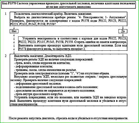
Code P1579 Throttle actuator control system, zero position adaptation interrupted due to external conditions
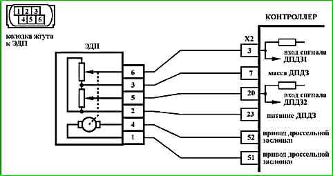
Code P1579 is stored if:
- - ignition enabled;
- - adaptation of the throttle position zero has been interrupted due to incorrect external conditions.
The malfunction indicator lights up 5 s after the malfunction code has occurred.
Description of checks
The sequence corresponds to the numbers on the map.
- 1 Using the diagnostic tool, check for codes P0112, P0113, P0116, P0117, P0118, P2122, P2123, P2127, P2128, P2138. If the codes are present, then the troubleshooting should begin with these codes.
- 2 The conditions for carrying out the zero adaptation of the throttle valve are checked.
Diagnostic information
If the P1579 fault is detected, the engine management system will operate in emergency mode until the end of the current trip:
- - the electric throttle drive is de-energized;
- - engine speed limitation (up to 2500 rpm depending on the accelerator pedal position).
The diagnostic tool in the "1 - Parameters; 1 - General view" mode displays the percentage of opening of the WDKBA throttle valve.
When the ignition is turned on, the controller performs:
- - return spring test;
- - check of the throttle position with no power electric drive;
- - adaptation of the zero position of the throttle valve;
- - test of the direct spring.
If the controller is new (adaptation is carried out for the first time), then all the above procedures are performed immediately after turning on the ignition for 1.5 seconds.
If the controller was taught earlier, then immediately after turning on the ignition, a test of the return spring is performed. The remaining procedures will be performed within the next 30 seconds if none of the following conditions are violated during this time:
- - the engine is not cranking;
- - the vehicle is not moving;
- - the accelerator pedal is not pressed;
- - the engine temperature is above 5 °C and below 100 °C;
- - the ambient air temperature is above 5 °C.
The P1579 code indicates that the first learning of the controller was interrupted due to violation of the adaptation conditions (see above).
If the throttle actuator is de-energized, the throttle valve is held in the Limp home position (7-8%) by means of the direct and return springs.
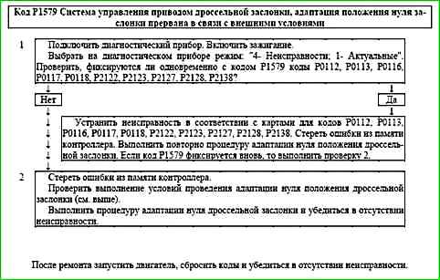
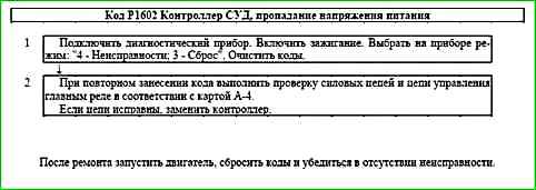
Code P1602 ECU, loss of power supply voltage
Code P1602 is recorded if:
- - ignition is on;
- - the controller has detected a loss of power supply voltage.
When this code occurs, the malfunction indicator does not light.
Description of tests
The sequence corresponds to the numbers on the map.
- 1 Reset the code.
- 2 Check the power circuits in according to the A-4 chart.
Diagnostic information
If the controller is replaced, it is necessary to perform the throttle valve zero adaptation procedure and the misfire diagnostic function adaptation procedure
Code P1603 Throttle actuator control monitoring, monitoring module malfunction
Code P1603 is set if:
- - ignition is on;
- - internal tests of the controller have determined a malfunction of the monitoring module.
The malfunction indicator lights up 5 seconds after the malfunction code has occurred.
Description of tests
The sequence corresponds to the numbers on the map.
1 If the malfunction is recorded periodically, it is necessary to replace the controller.
Diagnostic information
From the moment the ignition is turned on until the moment the main relay is disconnected, the controller performs internal checks aimed at determining the malfunction of the processor hardware.
Some of the checks are performed once when the ignition is turned on and off.
Some of the checks are performed cyclically.
When a malfunction is detected, the processor is reset and initialized.
If the controller is replaced, it is necessary to perform the throttle zero adaptation procedure and the misfire diagnostic function adaptation procedure

Code P2100 Throttle actuator control circuit open
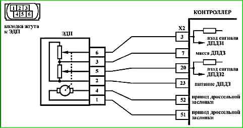
Code P2100 is set if:
- - the engine is running;
- - the throttle actuator self-diagnosis has determined that output no load.
The fault indicator lights up 5 s after the fault code has occurred.
Description of checks
The sequence corresponds to the numbers on the map.
- 1 Checks for a permanent fault.
- 2 Checks the electric motor circuit for an open circuit.
- 3 Checks the throttle actuator power supply circuit for an open circuit.
Diagnostic information
The controller uses a throttle actuator driver with a self-diagnostic function. It can detect faults such as open, short to ground or short to power in the control circuit.
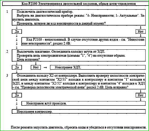
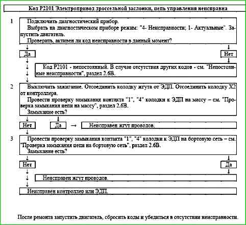
Code P2101 Throttle Actuator Control Circuit Malfunction
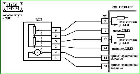
Code P2101 is set if:
- - the engine is running;
- - self-diagnosis of the throttle actuator driver has detected a malfunction.
The malfunction indicator lights up 5 s after the malfunction code has occurred.
Description of tests
The sequence corresponds to the numbers on the map.
- 1 The presence of a permanent malfunction is checked.
- 2 The presence of a short to ground in the electric actuator control circuit is checked.
- 3 The presence of a short to the on-board network in the control circuit is checked. electric drive.
Diagnostic information
The controller uses an electric throttle drive driver with a self-diagnostic function. It can detect faults such as an open, short to ground, or short to power in the control circuit.
Code P2122 Pedal Position Sensor A Circuit Low Input
Code P2122 is set if:
- - ignition is on;
- - signal from accelerator pedal position sensor A (UPWG1ROH) is less than 0.4 V for 0.2 s.
The malfunction indicator lights up after 5 s after e occurrence of the fault code.
Description of tests
The sequence corresponds to the numbers on the map.
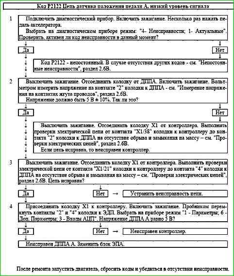
- 1 Using the diagnostic tool, it is checked whether the P2122 code is active at the time of diagnostics.
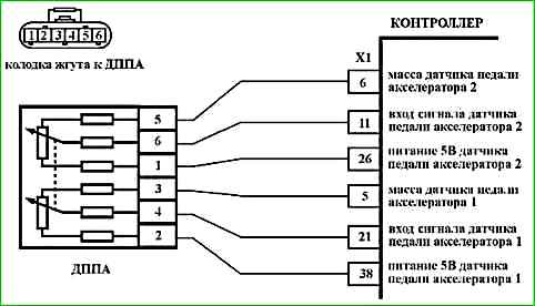
- 2 The controller is checked: the reference voltage of 5 V from the controller should be supplied to contact "2" of the connector to the DPPA.
- 3 The signal circuit is checked for an open circuit or short circuit to ground.
- 4 The controller is checked: when contacts "2" and "4" of the connector to the DPPA are shorted using a tester, the DPPA A signal on the diagnostic tool should change.
Diagnostic information
If a fault in the DPPA A circuit is detected, the engine management system will operate in emergency mode until the end of the current trips.
The following emergency modes are possible:
- - engine power limitation if the DPPA B circuit is in good condition;
- - idle speed if the DPPA A and DPPA B circuits are faulty.
The diagnostic device in mode "1 - Parameters; 6 - Additional Parameters; 3 - ADC inputs" shows the signals of DPPA A (UPWG1ROH) and DPPA B (UPWG2ROH) in volts.
The signals of DPPA A and DPPA B increase proportionally to the pressing of the accelerator pedal. At any position of the accelerator pedal, the signal of DPPA A should be twice as large as the signal of DPPA B.
When the accelerator pedal is released, the signal of DPPA A should be in the range of 0.46 ... 0.76 V, the signal of DPPA B should be in the range of 0.23 ... 0.38 V.
To calculate the accelerator pedal position, expressed as a percentage (WPED), the minimum signal from UPWG1ROH and 2 × UPWG2ROH is used.
Each time the ignition is turned on, the controller determines the zero position of the accelerator pedal. The position 100% is achieved at a voltage of 2.30 V / 1.15 V from the DPPA A / DPPA B sensor.
