Diagnostic code maps P0136 to P0351 with the ME17.9.71 Niva Chevrolet controller
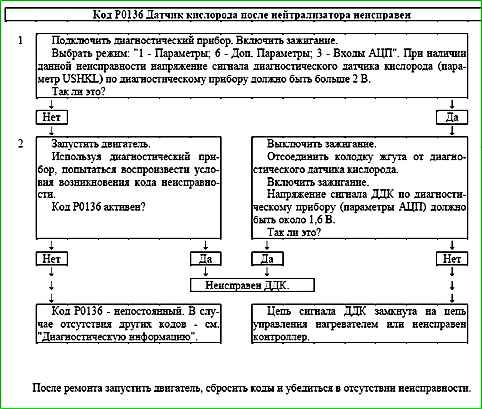
Code P0136 Oxygen sensor after the neutralizer is faulty
Code P0136 is recorded if:
- - the engine has been running for a time sufficient to warm up the oxygen sensor (up to 30 min, determined coolant temperature at start);
- - the DDC signal repeats the shape of the heater control signal (shorting the output signal circuit to the heater control circuit).
The malfunction indicator lights up on the 3rd trip after a persistent malfunction has occurred.
Description of checks
The sequence corresponds to the numbers on the map.
- The value of the output signal voltage of the diagnostic oxygen sensor is checked.
- The presence of a permanent malfunction is checked.
- The serviceability of the sensor is checked
Diagnostic information
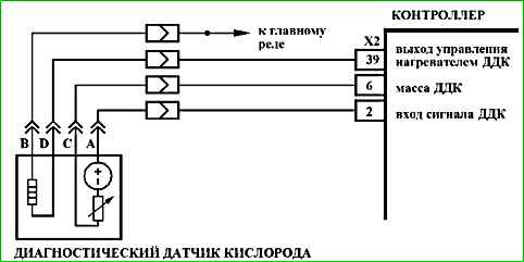
The voltage at contact "A" of a cold diagnostic oxygen sensor is 1.6 V.
For a warmed-up sensor, the signal voltage when operating in feedback mode, at partial loads and with a serviceable neutralizer in steady-state mode varies in the range from 590 to 750 mV.
An intermittent fault may be caused by the following faults:
Incorrect wiring harness route. Make sure that the sensor lead does not touch any exhaust system components.
Too lean air/fuel mixture. Run diagnostics of the fuel supply system according to the A-6 chart.
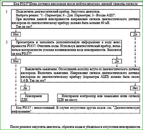
Code P0137 Oxygen sensor circuit after neutralizer, low signal level

Code P0137 is set if:
- - the engine has been running for a period of time sufficient to warm up the oxygen sensor (up to 30 minutes, determined by the coolant temperature at start-up);
- - the cold oxygen sensor signal voltage (parameter USHKL) is less than 60 mV;
or for 40 seconds the warmed-up oxygen sensor signal voltage (parameter USHKL) is less than 60 mV, while the system delivers fuel in feedback mode based on the UDC signal.
The malfunction indicator lights up on the 3rd trip after a persistent malfunction has occurred.
Description of tests
The sequence corresponds to the numbers on map.
- Checks the output voltage value of the diagnostic oxygen sensor.
- Checks for a permanent fault.
- Checks the sensor for serviceability.
Diagnostic information
The voltage at contact "A" of a cold diagnostic oxygen sensor is 1.6 V.
For a warmed-up sensor, the signal voltage when operating in feedback mode, at partial loads and with a serviceable neutralizer in steady-state mode varies in the range from 590 to 750 mV.
A fault of an intermittent nature can be caused by the presence of the following faults:
Unreliable connection of the contacts of the connectors of the ignition system harness, sensor and controller. Inspect the sensor and controller connectors, harness pads for completeness and correctness of articulation, damage to locks, presence of damaged contacts and quality of connection of contacts with the wire.
Incorrect wiring harness route. Make sure that the branch to the sensor does not touch the elements of the exhaust system.
Excessively lean fuel-air mixture. Run diagnostics of the fuel supply system according to the A-6 chart.
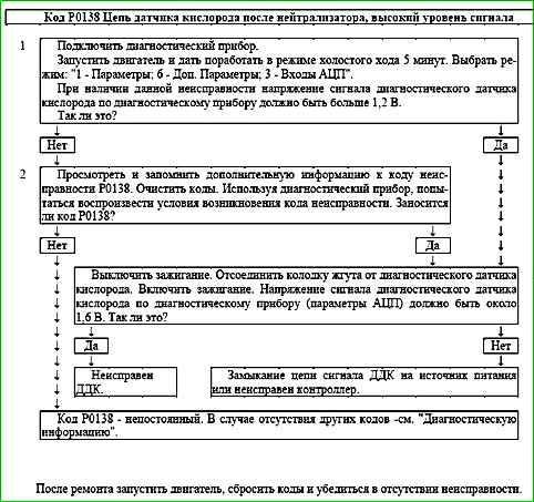
Code P0138 Oxygen sensor circuit after neutralizer, high signal level

Code P0138 is entered if:
- - the engine has been running for a period of time sufficient to warm up the oxygen sensor (up to 30 minutes, determined by the coolant temperature at start-up);
- - the diagnostic signal voltage o oxygen sensor USHKL is greater than 1.2 V for 5 s.
The malfunction indicator lights up on the 3rd trip after a persistent malfunction has occurred.
Description of tests
The sequence corresponds to the numbers on the map.
- The value of the output voltage of the diagnostic oxygen sensor is checked.
- The presence of a permanent malfunction is checked.
- The serviceability of the sensor is checked.
Diagnostic information
The voltage at contact "A" of a cold diagnostic oxygen sensor is 1.6 V.
For a warmed-up sensor, the signal voltage when operating in feedback mode, at partial loads and with a serviceable neutralizer in steady-state mode varies in the range from 590 to 750 mV.
An intermittent fault may be caused by the following faults:
Incorrect wiring harness routing. Make sure that the sensor lead does not touch any exhaust system components.
Silicon contamination of the sensor surface. Check the working part of the sensor for white deposits.
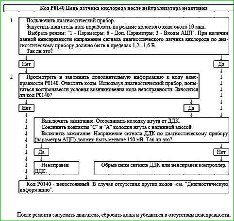
Code P0140 After-catalyst oxygen sensor circuit inactive

Code P0140 is set if:
- - the engine has been running for a period of time sufficient to warm up the oxygen sensor (up to 30 minutes, determined by the coolant temperature at start-up);
- - the signal voltage of the diagnostic oxygen sensor USHKL is in the range of 1.2...1.6 V.
The malfunction indicator lights up on the 3rd trip after a persistent malfunction has occurred.
Description of tests
The sequence corresponds to the numbers on the map.
- The value of the output signal voltage of the diagnostic oxygen sensor is checked.
- The presence of a permanent malfunction is checked.
- The serviceability of the sensor is checked.
Diagnostic information
The voltage at contact "A" of a cold diagnostic oxygen sensor is 1.6 V.
For a warmed-up sensor, the signal voltage when operating in feedback mode, at partial loads and with a serviceable neutralizer in steady-state mode varies in the range from 590 to 750 mV.
An intermittent malfunction may be caused by the presence of the following malfunctions:
Unreliable connection of the contacts of the ignition system harness pads, sensor and controller. Inspect the sensor and controller connectors, harness pads for completeness and correctness of articulation, damage to locks, presence of damaged contacts and quality of connection of contacts with the wire.
If simultaneously with the code P0140 the following are recorded:
- code P0036, then the most likely cause of the malfunction is disconnection of the diagnostic oxygen sensor from the wiring harness and troubleshooting should begin with the P0036 code map.
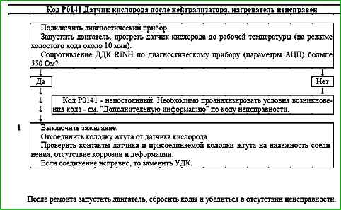
Code P0141 Sensor oxygen after the neutralizer, the heater is faulty

Code P0141 is entered if:
- - the engine is running;
- - the temperature of the neutralizer calculated by the controller is above the threshold;
- - the resistance of the DDK calculated by the controller is above the threshold.
The malfunction indicator lights up on the 3rd trip after a persistent malfunction occurs.
Description checks
The sequence corresponds to the numbers on the map.
- The reliability of the oxygen sensor connection to the wiring harness is checked.
Diagnostic information
During operation, the controller calculates the resistance of the sensing element of the oxygen sensor, which depends on the operating temperature of the sensor. It, in turn, is determined by the temperature of its heater and exhaust gases. Depending on the engine operating mode, the resistance of the oxygen sensor can vary in the range of 90 ... 550 Ohm.
If the code P0036 is recorded simultaneously with the code P0141, then troubleshooting should begin with the code P0036 map.
The cause of the code P0141 may be:
- - installation of the oxygen sensor another type;
- - unreliable contact in the harness and sensor pads.
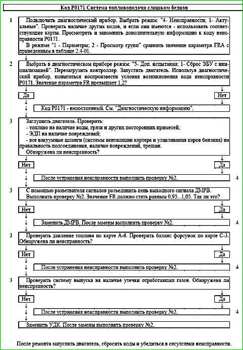
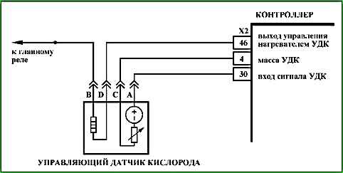
Code P0171 Fuel supply system too lean
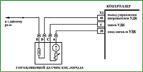
Code P0171 is set if:
- - engine running ;
- - fuel supply control is performed in feedback mode based on the oxygen sensor signal (B_LR = "Yes");
- - fuel supply adaptation function is activated (B_LRA = "Yes");
- - the FRA parameter value is outside the upper limit of the permissible range (greater than 1.25).
The malfunction indicator lights up on the 3rd trip after a persistent malfunction occurs.
Description of checks
The sequence corresponds to the numbers on the map.
- The diagnostic information.
- With the engine running, the diagnostic tool simulates the conditions for the occurrence of a malfunction.
- Systems and components whose malfunction may lead to the occurrence of a code are checked.
- When carrying out re-check No. 2 after eliminating the possible cause of the malfunction, the value of the FR parameter should not go beyond the range of 1±0.1.
Diagnostic information
An intermittent malfunction may be caused by presence of the following faults:
Unreliable connection of the contacts of the ignition system harness pads, sensor and controller. Inspect the sensor and controller connectors, harness pads for completeness and correctness of articulation, damage to the locks, the presence of damaged contacts and the quality of the connection of the contacts with the wire.
Incorrect wiring harness route. Make sure that the lead to the sensor does not touch any components of the exhaust system.
Harness damage. Check the harness for damage. If the harness appears normal, move the corresponding connector and harness while simultaneously observing the readings of the diagnostic tool .
Unreliable grounding of the controller. Check the reliability of the connection of the ignition system harness wires to the cylinder block. Make sure that the contacts are not contaminated.
UDC degradation. Replace UDC.
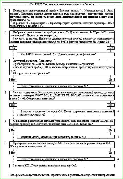
Code P0172 Fuel injection system too rich
Code P0172 is set if:
- - engine running;
- - control fuel supply is carried out in the feedback mode according to the signal of the control oxygen sensor (B_LR = "Yes");
- - the fuel supply adaptation function is activated (B_LRA = "Yes");
- - the value of the FRA parameter goes beyond the lower limit of the permissible range (less than 0.75).
The malfunction indicator lights up on the 3rd trip after a persistent malfunction occurs.
Description of tests
The sequence corresponds to the numbers on the map.
- The diagnostic information is analyzed.
- The conditions for the occurrence of the fault are simulated with the diagnostic device while the engine is running. malfunctions.
- The systems and components whose malfunction may lead to the code are checked.
- When conducting a repeat check No. 2 after eliminating the possible cause of the malfunction, the value of the FR parameter should not go beyond the range 1 ±0.1.
Diagnostic information
An intermittent malfunction may be caused by the following malfunctions:
Poor connection of the ignition system harness pad contacts, sensor and controller. Inspect the sensor and controller connectors, harness pads for completeness and correctness of articulation, damage to locks, presence of damaged contacts and quality of connection of contacts with the wire.
Incorrect wiring harness route. Make sure that the branch to sensor does not touch the exhaust system components.
Harness damage. Check the harness for damage. If the harness appears normal, move the corresponding connector and harness while simultaneously observing the readings of the diagnostic device.
Unreliable grounding of the controller. Check the reliability of the connection of the ignition system harness wires to the b cylinder block. Make sure that the contacts are not contaminated.
UDC degradation. Replace UDC.
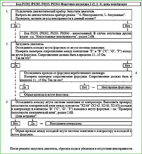
Code P0201 (P0202, P0203, P0204) Injector cylinder 1 (2, 3, 4), circuit faulty
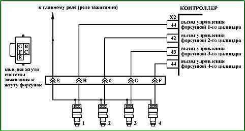
Code P0201 (P0202, P0203, P0204) is set if:
- - the engine is running;
- - the injector driver self-diagnosis has determined that there is no load on one or more outputs.
The malfunction indicator lights up 5 seconds after the malfunction code has occurred.
Description of tests
The sequence corresponds to the numbers on the map.
- The presence of a permanent malfunction is checked.
- The injector harness is checked.
- The resistance of the circuit between the ignition harness connector to the controller and the connector to the injector harness.
- The resistance of the injector of the non-working cylinder is checked.
Diagnostic information
The controller uses an injector driver with a self-diagnostic function. It can detect faults such as open, short to ground or short to power in the injector control circuits.
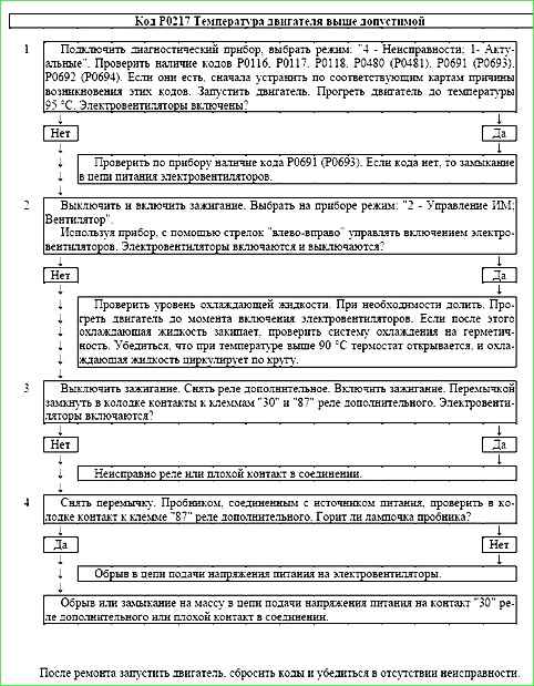
Code P0217 Engine temperature above permissible
Code P0217 is entered if:
- - the engine runs for more than 3 minutes;
- - coolant temperature TMOT is above 120 °C;
- - there are no fault codes P0116, P0117, P0118.
The malfunction indicator lights up 5 seconds after the fault code occurs.
Description of tests
The sequence corresponds to the numbers on the map.
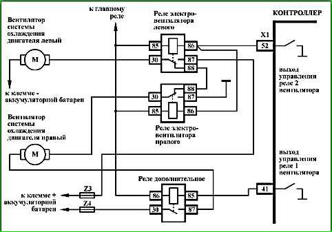
- On a cold engine, in the absence of codes P0116, P0117, P0118, P0480 (P0481), P0691 (P0693), P0692 (P0694) the electric fan should not work.
- The controller's ability to control the electric fan relay is checked.
- The electric fan relay is checked for serviceability.
- The electric fan control circuit is checked for serviceability.
Diagnostic information
The cause of engine overheating may be a faulty thermostat, no or low level of coolant in the engine cooling system, a non-working electric fan.
Code P0217 may occur falsely, with a faulty coolant temperature sensor or poor connector contacts, or poor ground of the ignition system harness.
After starting a cold engine, the temperature should rise evenly to 85 ... 95 ° C, then stabilize when the thermostat opens.
After warming up the entire volume of coolant, the temperature also increases uniformly until the electric fans are turned on at a temperature above 101 °C.
After the electric fans are turned on, the temperature decreases uniformly until the electric fans are turned off at a temperature below 95 °C.
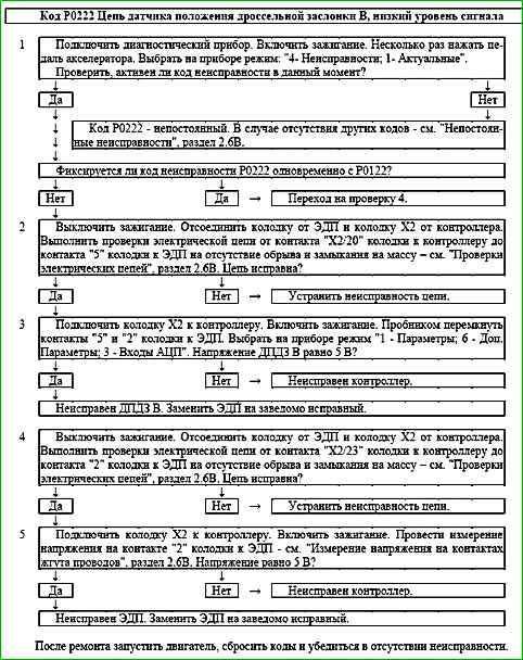
Code P0222 Throttle position sensor B circuit, low signal level
The P0222 code is stored if:
- - ignition is on;
- - throttle position sensor UDKP2 signal voltage is less than 0.25 V for 0.12 s.
The malfunction indicator lights up 5 s after the malfunction code has occurred.
Description of tests
The sequence corresponds to the numbers on the map.
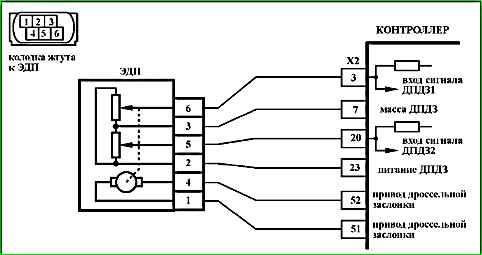
- 1 Using the diagnostic tool, it is checked whether the P0222 code is active at the moment diagnostics. If only the P0222 code is recorded, then the fault must be looked for in the TPS A signal circuit.
If the P0122 and P0222 codes are recorded simultaneously, then the fault must be looked for in the TPS power supply circuit A and TPS B.
- 2 The circuit from contact "X2/20" of the controller to contact "5" of the EDP is checked.
- 3 The controller is checked: when contacts "5" and "2" of the EDP connector are short-circuited using a tester, the TPS B signal on the diagnostic device should change.
- 4 The circuit from contact "X2/23" of the controller to contact "2" of the EDP is checked.
- 5 The controller is checked: a 5 V reference voltage from the controller should be supplied to contact "2" of the EDP connector.
Diagnostic information
If a malfunction of the TPS B circuit is detected, the engine management system will operate in emergency mode until the end of the current trip.
The following emergency modes:
- - engine power limitation if the TPS A circuit is in good condition;
- - de-energization of the throttle actuator and engine speed limitation (2500 rpm) if the TPS A and TPS B circuits are faulty.
The diagnostic device in mode "1 - Parameters; 6 - Additional Parameters; 3 - ADC inputs" shows the signals of TPS A (UDKP1) and TPS B (UDKP2) in volts.
When the throttle valve is opened, the TPS A signal increases, the TPS B signal decreases.
When the throttle valve is fully closed, the TPS A signal should be in the range of 0.3 ... 0.6 V, the TPS B signal should be in the range of 4.4 ... 4.7 V.
The sum of the TPS A and TPS B signals should be equal to (5 ± 0.1) V at any throttle position.
In case of replacing the ECM or ECM controller, or resetting the controller using a diagnostic tool (mode "5 - Additional tests; 1 - ECU reset with initialization"), it is necessary to perform the throttle zero adaptation procedure dampers.
To do this, turn on the ignition with the vehicle stationary, wait 30 seconds, turn off the ignition, wait for the main relay to disconnect.
Adaptation will be interrupted if:
- - the engine is cranking;
- - the vehicle is moving;
- - the accelerator pedal is pressed;
- - the engine temperature is below 5 °C or above 100 °C;
- - the ambient air temperature is below 5 °C.
If the throttle actuator is de-energized, the throttle valve is held in the Limp home position (7-8%) by means of the direct and return springs.
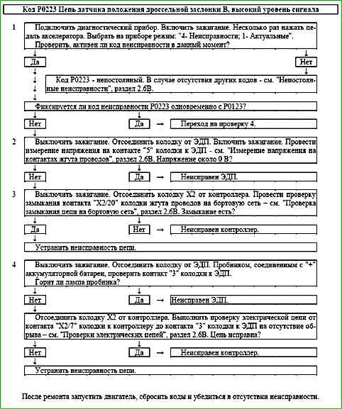
Code P0223 Throttle Position Sensor B Circuit High Voltage

Code P0123 is stored, if:
- - ignition is on;
- - throttle position sensor UDKP2 signal voltage is more than 4.75 V for 0.12 s.
The malfunction indicator lights up 5 s after the malfunction code has occurred.
Description of tests
The sequence corresponds to the numbers on the map.
- 1 Using a diagnostic tool, check whether the P0223 code is active at the time of diagnostics.
If only the P0223 code is recorded, then the malfunction should be looked for in the signal circuit of TPS B.
If the P0123 and P0223 codes are recorded simultaneously, then the malfunction should be looked for in the ground circuit of TPS A and TPS B.
- 2 The voltage in the TPS signal circuit B is checked with the sensor disconnected. Voltage should be around 0 V.
- 3 The signal circuit is checked for a short to power.
- 4 The ground circuit of TPS A and TPS B is checked.
Diagnostic information
If a fault in the TPS B circuit is detected, the engine management system will operate in emergency mode until the end of the current trip.
The following emergency modes are possible:
- - engine power limitation if the TPS A circuit is intact;
- - throttle actuator power is cut off and engine speed is limited (2500 rpm) if the TPS A and TPS B circuits are faulty.
The diagnostic tool in the mode "1 - Parameters; 6 - Additional Parameters; 3 - ADC Inputs" shows signals of TPS A (UDKP1) and TPS B (UDKP2) in volts.
When the throttle valve is opened, the TPS A signal increases, the TPS B signal decreases.
When the throttle valve is fully closed, the TPS A signal should be in the range of 0.3…0.6 V, the TPS B signal should be in the range of 4.4…4.7 V.
The sum of the TPS A and TPS B signals should be equal to (5±0.1) V at any throttle position.
In case of replacing the ECM or ECM controller, or resetting the controller using a diagnostic tool (mode "5 - Additional tests; 1 - ECU reset with initialization"), it is necessary to perform the adthrottle valve zero adjustment.
To do this, turn on the ignition with the vehicle stationary, wait 30 seconds, turn off the ignition, wait for the main relay to disconnect.
Adaptation will be interrupted if:
- - the engine is cranking;
- - the vehicle is moving;
- - the accelerator pedal is pressed;
- - the engine temperature is below 5 °C or above 100 °C;
- - the ambient air temperature is below 5 °C.
If the throttle valve electric drive is de-energized, the throttle valve is held in the Limp home position (7-8%) by means of the direct and return springs.
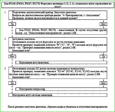
Code P0261 (P0264, P0267, P0270) Injector Cylinder 1 (2, 3, 4), Control Circuit Short to Ground
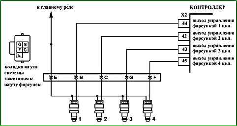
Code P0261 (P0264, P0267, P0270) is recorded if:
- - the engine is running;
- - self-diagnosis of the injector driver has detected a short circuit to ground in one or more outputs.
The malfunction indicator lights up 5 seconds after the malfunction code has occurred.
Description of tests
The sequence corresponds to the numbers on the map.
- Checks for a permanent malfunction.
- Checks for a short circuit in the injector harness.
- Checks for a short circuit to ground in the ignition system harness.
Diagnostic information
The controller uses an injector driver, having a self-diagnostic function. It can detect faults such as open circuit, short circuit to ground or power supply of the injector control circuits.
Code P0262 (P0265, P0268, P0271) Injector cylinder 1 (2, 3, 4), control circuit short to on-board network
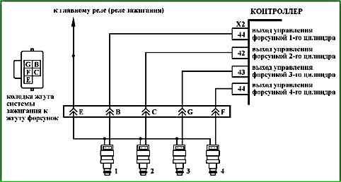
Code P0262 (P0265, P0268, P0271) is recorded if:
- - the engine is running;
- - self-diagnosis of the injector driver has determined a short circuit of one or more outputs to the power source.
The malfunction indicator lights up 5 seconds after the malfunction code has occurred.
Description of checks
The sequence corresponds to the numbers on the map.
- The presence of a permanent malfunction is checked.
- Checked presence of a short circuit in the ignition system harness.
- The injector is checked for serviceability.
Diagnostic information
The controller uses an injector driver with a self-diagnostic function. It can detect faults such as open, short to ground or short to power in the injector control circuits.
The occurrence of the P0262 (P0265, P0268, P0271) code can be caused by a fault in the corresponding injector (interturn short).
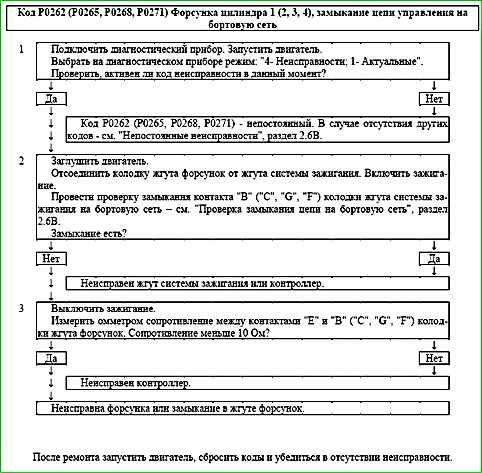
Code P0300 Random/Multiple Misfires Detected ignition
Code P0301 (P0302, P0303, P0304) Cylinder 1 (2, 3, 4), misfire detected
Code P0363 Misfire detected, fuel supply to non-firing cylinders is cut off

Codes P0300, P0301 (P0302, P0303, P0304), P0363 are set if:
- - the engine is running;
- - the NMOT engine speed is in the range of 600...5300 rpm;
- - the system is performing misfire recognition diagnostics (B_LUSTOP = "No");
- - the crankshaft rotation irregularity measured by the controller exceeds the threshold;
- - there is no P0335 fault code.
If the system detects misfires that affect toxicity, the malfunction indicator lights up on the 3rd trip after the occurrence of a stable oh malfunction.
If the system detects misfires that damage the catalytic converter, the malfunction indicator starts flashing immediately after a persistent malfunction occurs.
In order to protect the catalytic converter, the fuel supply can be shut off in those cylinders in which misfires were registered.
Description of tests
The sequence corresponds to the numbers on the map.
- Check if misfires are recorded at the time of request.
- Perform an ignition system test.
- Perform a fuel supply system test.
- Perform an intake system test.
- Perform a compression test.
Additional tests
If misfires are intermittent, it is necessary to check:
- - reliability of fastening of ground terminals of ignition system harness;
- - mechanical damage of engine (low compression, damage of pistons, camshaft, valves, etc.);
- - intake system for absence of air leaks (check intake system after MAF for absence of air leaks, make sure that vacuum hoses are connected securely and are not damaged);
- - malfunction of elements of fuel supply system (see. map A-6);
- - malfunction of ignition system components (see map A-3);
- - crankshaft position sensor (CPS) fastening;
- - radial runout of the damper crown (sensor disk) should be no more than 0.4 mm.
Diagnostic information
The diagnostic tool in the "1 - Parameters; 6 - Additional parameters; 1 - Misfires" mode shows:
- - misfire counter FZABGZIL1(2, 3, 4);
- - misfire recognition diagnostic pause bit B_LUSTOP.
If simultaneously with codes P0300, P0301 (P0302, P0303, P0304), P0363 are recorded ignition coil or injector control circuit fault codes, then troubleshooting should begin with the corresponding control circuit fault code map.
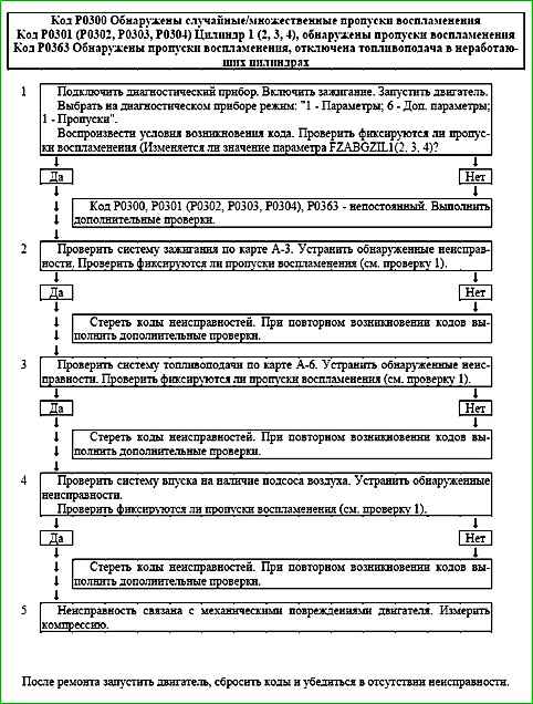
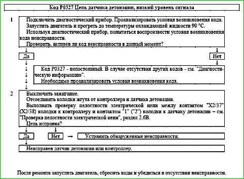
Code P0327 Knock Sensor Circuit Low Voltage
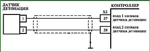
Code P0327 is set if within 5 seconds:
- - engine speed NMOT is greater than 2000 rpm;
- - knock control is enabled VK_R = "Yes";
- - knock sensor signal amplitude is below threshold.
The malfunction indicator lights up on the 3rd trip after a persistent malfunction has occurred.
Description of tests
The sequence corresponds to the numbers on the chart.
- The existence of conditions for the occurrence of code P0327 is checked.
- The serviceability of the wires is checked, connecting the knock sensor to the controller.
Diagnostic information
It is necessary to check the knock sensor connector for foreign liquids (motor oil), dirt and dust.
It is necessary to check the tightening torque of the knock sensor mounting bolt. If the tightening torque is insufficient, the amplitude of the sensor signal decreases.
See "Intermittent faults"
See "Checking the knock suppression system", chart C-5.
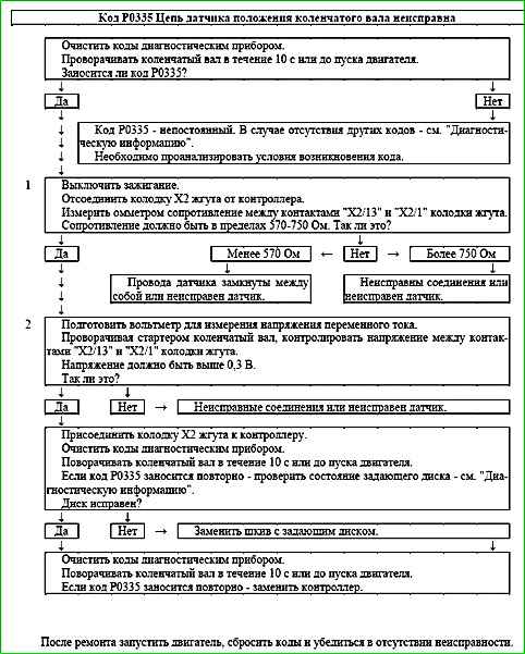
Code P0335 Crankshaft Position Sensor Circuit Malfunction
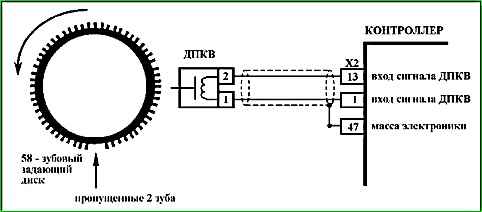
Code P0335 is set if:
- - the crankshaft turns;
- - the MAF signal changes above a certain value;
- - there is no signal from the crankshaft position sensor.
When this code occurs, the malfunction indicator does not light.
Description of tests
The sequence corresponds to the numbers on the chart.
- The wires and resistance of the crankshaft position sensor are checked. The resistance may change slightly with increasing temperature.
- The sensor output signal must have an AC voltage amplitude of at least 0.3 V at crankshaft speed
Diagnostic information
A faulty contact in the sensor or controller socket may indicate a may cause an intermittent code P0335 to be set.
Check the timing wheel on the crankshaft pulley for tooth damage, runout (the radial runout of the damper crown should be no more than 0.4 mm) or other damage.
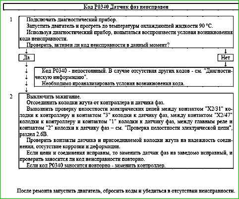
Code P0340 Phase sensor malfunction
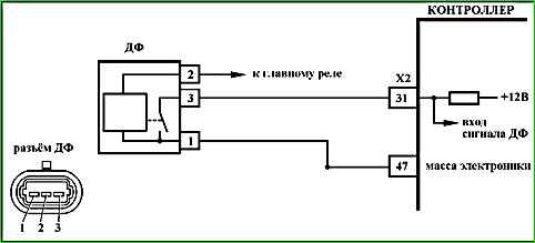
Code P0340 is entered if:
- - the crankshaft turns;
- - the pulse sequence is non-periodic.
The malfunction indicator lights up on the 3rd trip after a persistent malfunction has occurred.
Description of tests
The sequence corresponds to the numbers on the map.
- The presence of a permanent malfunction is checked.
- The reliability of the phase sensor connection to the harness is checked wires.
Diagnostic information
An intermittent malfunction may be caused by the following malfunctions.
Unreliable connection of the contacts of the ignition system harness pads, sensor and controller.
Inspect the sensor and controller connectors, harness pads for reliability of connection, absence of damage to the pad locks and damaged contacts.
Harness damage. Check harness for damage.
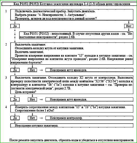
Code P0351 (P0352) Ignition Coil Cylinder 1-4 (2-3) Control Circuit Open

Code P0351 (P0352) is set if:
- - the engine is running;
- - self-diagnosis has recorded no current through the ignition coil.
The malfunction indicator lights up 5 seconds after the malfunction code has occurred.
Description of tests
The sequence corresponds to the numbers on the map.
- The presence of a permanent malfunction is checked.
- The serviceability of the power supply circuit is checked.
- The serviceability of the control circuit is checked.
- The serviceability of the ignition coil is checked.
Diagnostic information
The ME17.9.71 controller constantly monitors the current through the ignition coil. If there is no current or its value is insufficient, a fault code is recorded.
