Each diagnostic chart consists of two pages: "Additional information" and "Troubleshooting chart"
Additional information" contains the conditions for entering the fault code, connection diagrams and explanations for the blocks of the fault search chart
Finding and eliminating the fault is carried out in accordance with the fault search sequence chart.
When diagnosing any fault, you must always start with checking the diagnostic circuit.
Checking the diagnostic circuit leads to other charts. Using the fault code chart without first checking the diagnostic circuit is not allowed.
This can lead to an incorrect diagnosis and replacement of serviceable parts.
The engine management system uses a controller that is located in a hard-to-reach place.
Since the terminals inside the connector blocks are inaccessible for connecting external measuring devices, then to check the serviceability of the harness circuits injection system, it is necessary to use a signal splitter corresponding to this type of controller, connected between the controller and the wiring harness.
Diagnostic cards "A" (initial check cards and trouble code cards)
Card "A" Checking the diagnostic circuit
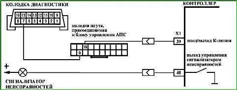
Description of tests
The sequence corresponds to the numbers on the card.
Checks the serviceability of the indicator faults.
If the indicator does not light when the ignition is turned on, then it is necessary to check the power supply to the ignition switch and the controller, as well as the connection of the controller to ground, using the A-1 map.
The possibility of transmitting serial data from the controller to the diagnostic device is checked.
If there is no signal, then the "X" symbol is displayed in the upper right corner. If the signal is present, a symbol in the form of arrows (pointing up and down) is displayed.
The serviceability of the vehicle anti-theft system (APS) is checked.
The ability to start the engine is checked.
The presence of fault codes in the controller memory that require repair is checked.
The presence of parameter deviations with the ignition on and the engine idling is checked.
If there are parameter deviations from the established standard values, the operability of the corresponding units or systems is checked using the cards in section "C" - "Diagnostic cards for checking engine management system units".
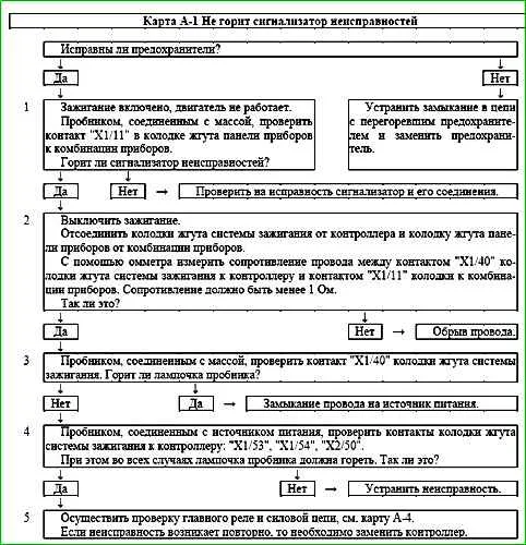
Map A-1 Malfunction indicator does not light
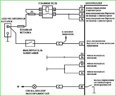
Circuit Description
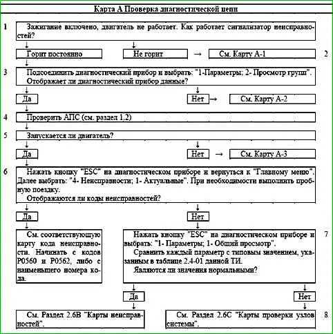
The malfunction indicator should light after the ignition is turned on and go out after the engine starts.
After the ignition is turned on, voltage is supplied to one of the indicator terminals. The controller controls the activation of the indicator by closing the second terminal to the ground "X1/40" of the controller.
Description of checks
The sequence corresponds to the numbers on the map.
- 1 - If the indicator does not light up during the check, then the fault must be looked for in the instrument panel harness.
- 2 - The circuit between the contacts "X1/40" of the controller and the connector to the instrument panel harness is checked for an open circuit.
- 3 - The circuit between the contacts "X1/40" of the controller and the connector to the instrument panel harness is checked for a short circuit to the power source.
- 4 - The serviceability of the circuits connecting the controller to the engine ground is checked.
- 5 - The presence of supply voltage is checked at the controller contacts: "X1/16", "X1/55", "Х1/56"
Map A-2 No data from diagnostic connector

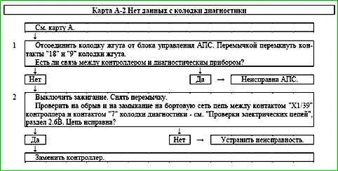
Circuit description
In the initial state, the circuit between contacts "9" and "18" of the APS control unit is open.
When connecting the diagnostic the device to the diagnostic socket and turning on the ignition, the APS control unit closes the circuit.
The control unit opens the circuit if the controller sends a request to communicate with the APS. Communication sessions occur when the ignition is turned on and off.
Description of checks
The sequence corresponds to the numbers on the map.
- 1 - If after closing contacts "18" and "9" of the harness connector, the connection between the diagnostic device and the controller is restored, then it is necessary to check the serviceability of the APS elements.
- 2 - The serviceability of the connection between the diagnostic connector (contact "7") and the controller (contact "X1/39") is checked.
Map A-3 (Sheet 1 of 2) Engine does not start
Description of tests
The sequence corresponds to the numbers on the map.
- 1 - Checking the state of the ECM using a diagnostic tool.
- 2 - Since the secondary circuit of the ignition coils is closed through the ground, the ground wire of the spark gap must be connected to the ground of the engine.
- 3 - Low fuel pressure can lead to an over-lean mixture. See Chart A-6.
- 4 - Cylinder compression and valve timing are checked.
Diagnostic information
At negative ambient temperatures, the engine may not start due to the presence of water or foreign substances in the fuel.
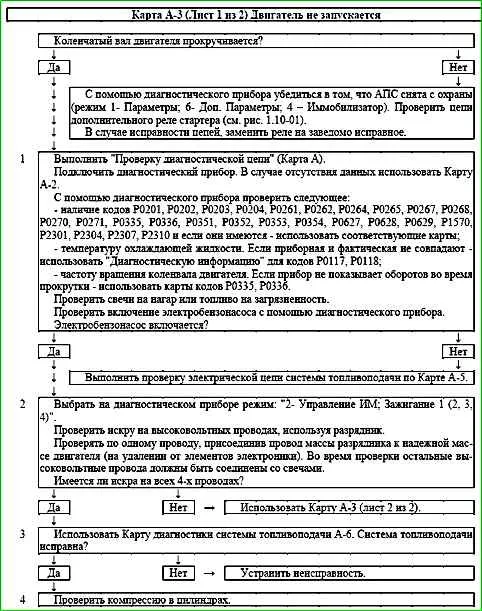
Chart A-3 (sheet 2 of 2) Engine does not start

Circuit description
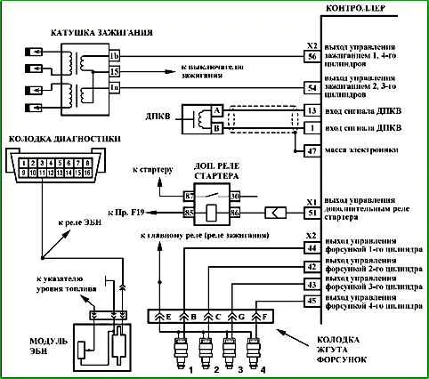
The engine ignition system has a block of two two-terminal ignition coils, whose high-voltage outputs of the secondary windings are connected by high-voltage wires to spark plugs 1, 4 and 2, 3 cylinders, respectively.
The primary circuits of the ignition coils are switched by power electronic keys located inside the controller.
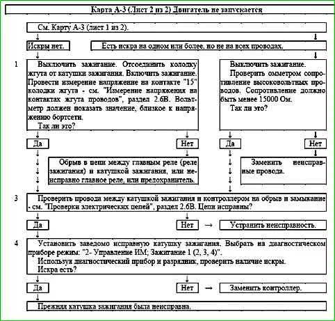
Description of tests
The sequence corresponds to the numbers on map.
In the ignition system, two spark plugs with high-voltage wires form the circuit of each coil. To obtain a spark, the ground wire of the spark gap must be connected to the engine ground.
- 1 - The presence of +12 V power on the ignition coil is determined.
- 2 - The serviceability of the high-voltage wires is checked.
- 3 - The presence of an open or short circuit in the ignition control circuits is determined.
- 4 - As a result of the check, the presence of a malfunction of the controller or ignition coil is determined.
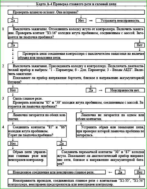
Map A-4 Checking the main relay and power circuit
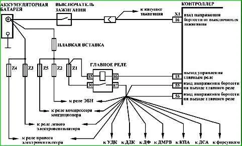
Circuit description
When the ignition is turned on, voltage from the ignition switch is supplied to the "X1/16" contact of the controller. The controller switches on the main relay via the "X1/15" contact, through which the supply voltage is supplied to the "X1/55" and "X1/56" contacts of the controller, as well as to the sensors and some controlled devices (adsorber purge valve, injectors, relays, etc.).
Description of tests
- 1 - Voltage is supplied to the "X1/16" contact of the controller from the ignition switch.
- 2 - The diagnostic device shows the voltage of the on-board network, determined by the controller based on the voltage at the "X1/55" and "X1/56" contacts. It should not differ by more than 1 V from the voltage at the battery.
- 3 - Battery voltage should be present at the "85" and "30" contacts of the harness connector. If power is present on both contacts, the tester light connected to ground should light when touched.
- 4 - The previous test determined the presence of voltage on the harness connector contact and "85". This test monitors the control circuit of the main relay, which must be shorted to ground by the controller.
- 5 - The serviceability of the main relay is checked.
The cause of an incorrect value of the on-board network voltage, determined by the controller by the voltage at the contacts "X1/55" and "X1/56", may be a short to ground in the power supply circuits to the relays and actuators, as well as incorrectly connected anti-theft devices.
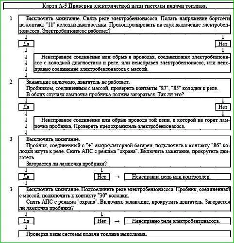
Map A-5 Checking the electrical circuit of the fuel supply system
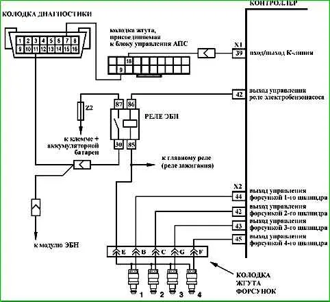
Description of the circuit
When the ignition is turned on, the controller turns on the electric fuel pump relay and the electric fuel pump starts working. If there are no reference pulses from the crankshaft position sensor (the engine is not running), the controller turns off the electric fuel pump 2 seconds after the ignition is turned on.
If the short-term activation of the electric fuel pump is repeated three times in a row, the next activation of the electric fuel pump will occur only when the controller receives signals from the crankshaft position sensor.
Description of checks
The sequence corresponds to the numbers on the map.
- Forced activation of the electric fuel pump is performed.
- The presence of +12 V voltage at the contacts of the electric fuel pump relay is checked.
- When the ignition is turned on and the engine is cranking, the controller should turn on the electric fuel pump.
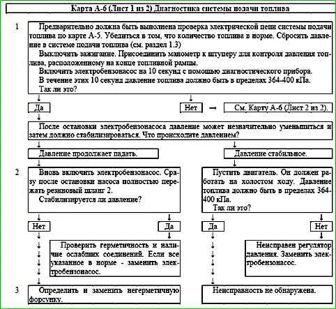
Map A-6 (Sheet 1 of 2) Fuel supply system diagnostics
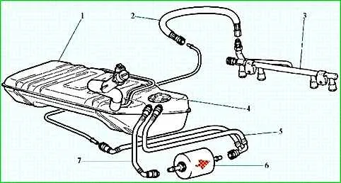
Chain description
When the ignition is turned on, the controller turns on the electric fuel pump.
It operates as long as the engine is running and the controller receives reference pulses from the crankshaft position sensor.
If there are no reference pulses, the controller turns off the electric fuel pump 2 seconds after the ignition is turned on.
The electric fuel pump supplies fuel to the fuel rail and, using the built-in regulator, maintains constant fuel pressure on the injectors.
The diagnostic connector has contact "11" for diagnosing the electric fuel pump.
When the engine is turned off and the ignition is off, the electric fuel pump can be turned on by supplying power to the specified diagnostic contact.
Description of tests
The sequence corresponds to the numbers on map.
- Check the fuel pressure and system operability.
- Check the tightness and connections of the line between the electric fuel pump and the injector rail.
- Stuck injector valve in the open position is best determined by checking the spark plugs for carbon deposits or moisture.
If it is impossible to determine the leakage of the injector by carbon deposits or wet spark plugs, it is necessary to check the balance of the injectors according to the C-3 map.
Diagnostic information
Deviation of fuel pressure can cause the following problems:
- - the starter turns the crankshaft, but the engine does not start;
- - the engine stalls, as if there is a malfunction in the ignition system;
- - high fuel consumption, loss of power;
- - unstable operation engine.
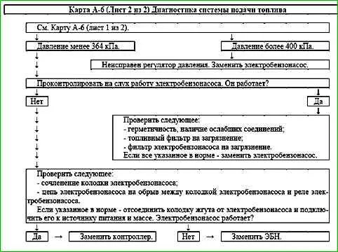
Map A-6 (Sheet 2 of 2) Fuel supply system diagnostics

Description of checks
The sequence corresponds to the numbers on the map.
4 - To check the fuel filter for contamination, measure the fuel pressure in the fuel line between the electric fuel pump and the fuel filter.
If the pressure value obtained in this way differs from the previously measured one (step 1 of the diagram) by more than 14 kPa, then the fuel filter must be replaced.
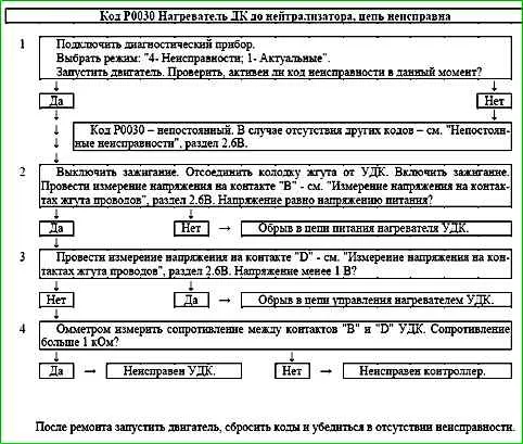
Code P0030 Heater DC to neutralizer, circuit faulty
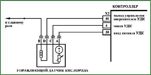
Code P0030 is recorded if:
- - the engine is running;
- - self-diagnosis of the heater driver has determined the absence of load at the output.
The malfunction indicator lights up 2 drive cycles after the occurrence of fault code.
Description of tests
The sequence corresponds to the numbers on the card.
- Checks for a permanent fault.
- Checks the power supply circuit of the UDC heater.
- Checks the control circuit of the UDC heater.
- Checks the serviceability of the UDC heater.
Diagnostic information
The ME17.9.71 controller uses a driver for the oxygen sensor heater, which has a self-diagnostic function.
It can detect faults such as an open circuit, short circuit to ground, or power supply of the heater control circuit.
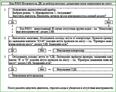
Code P0031 Heater DC to neutralizer, control circuit short to ground

Code P0031 is set if:
- - engine works;
- - self-diagnosis of the heater driver detected a short to ground at the output.
The fault indicator lights up 2 drive cycles after the occurrence of the fault code.
Description of tests
The sequence corresponds to the numbers on the map.
- Checks for a permanent fault.
- Detects a short to ground in the UDC heater control circuit.
- Checks the serviceability of the UDC heater.
Diagnostic information
The ME17.9.71 controller uses an oxygen sensor heater driver with a self-diagnostic function.
It can detect faults such as an open circuit, short to ground, or power supply in the heater control circuit.
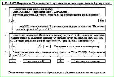
Code P0032 Heater DC to Catalytic Converter, Control Circuit Short to Battery

Code P0032 is set if:
- - the engine is running;
- - self-diagnosis of the heater driver has detected a short circuit to the on-board network at the output.
The malfunction indicator lights up 2 drive cycles after the malfunction code has occurred.
Description of tests
The sequence corresponds to the numbers on the map.
- The presence of a permanent malfunction is checked.
- The presence of a short circuit in the control circuit of the UDK heater to the on-board network is determined.
- The serviceability of the UDK heater is checked.
Diagnostic information
The ME17.9.71 controller uses a driver for the oxygen sensor heater, with a self-diagnostic function.
It can detect faults such as open circuit, short circuit to ground or power supply of the heater control circuit.
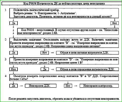
Code P0036 Heater after neutralizer, circuit malfunction
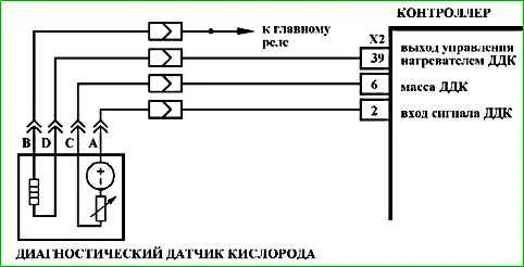
Code P0036 is recorded if:
- - the engine is running;
- - the heater driver self-diagnosis has determined that there is no load at the output.
The fault indicator lights up 2 drive cycles after the fault code has occurred.
Description of checks
The sequence corresponds to the numbers on the map.
- The presence of a permanent fault is checked.
- The power supply circuit of the ODK heater is checked.
- The control circuit of the ODK heater is checked.
- The serviceability of the ODK heater is checked.
Diagnostic information
The ME17.9.71 controller uses a driver for the oxygen sensor heater, which has a self-diagnosis function.
It can detect the presence of such faults as an open circuit, short circuit on the ground or power supply to the heater control circuit.
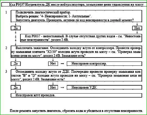
Code P0037 Heater after neutralizer, control circuit short to ground

The P0037 code is set if:
- - the engine is running;
- - the heater driver self-diagnosis has detected a short to ground at the output.
The malfunction indicator lights up 2 drive cycles after the occurrence of the trouble code.
Description of tests
The sequence corresponds to the numbers on the map.
- The presence of a permanent malfunction is checked.
- The presence of a short to ground in the control circuit of the DDK heater is determined.
- The serviceability of the DDK heater is checked.
Diagnostic information
In the controller ME17.9.71 uses a driver for the oxygen sensor heater, which has a self-diagnostic function.
It can detect the presence of such faults as an open circuit, a short circuit to ground or a short circuit to power supply in the heater control circuit.
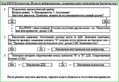
Code P0038 Heater after the neutralizer, control circuit short to on-board network

Code P0038 is entered if:
- - the engine is running;
- - the heater driver self-diagnostics detected a short circuit to the on-board network at the output.
The malfunction indicator lights up 2 drive cycles after the occurrence of the malfunction code.
Description of checks
The sequence corresponds to the numbers on the map.
- The presence of a permanent malfunction is checked.
- The presence of a short circuit in the heater control circuit is determined Oxygen sensor heater driver for on-board network.
- Checks the serviceability of the Oxygen sensor heater.
Diagnostic information
The ME17.9.71 controller uses an oxygen sensor heater driver with a self-diagnostic function.
It can detect the presence of such faults as an open circuit, short circuit to ground or power supply of the heater control circuit.
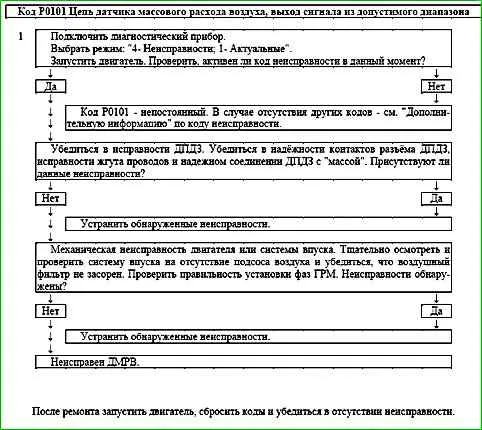
Code P0101 Mass Air Flow Sensor Circuit, Signal Out of Range
The P0101 code is set if the air flow, which depends on the engine speed NMOT and the throttle angle WDKBA, is note corresponds to the calculated one.
The malfunction indicator lights up on the 3rd trip after a persistent malfunction has occurred.
Description of checks
The sequence corresponds to the numbers on the map.
1 It is checked whether the controller currently detects a malfunction.
Diagnostic information
It is necessary to make sure that the following malfunctions are absent:
- - Incorrect readings of the throttle valve opening angle.
- - Clogged air filter in the air intake system. Replace the filter element if necessary.
- - Unaccounted air suction. Inspect and check the intake system for suction.
- - Incorrectly set timing phases. Check the timing belt for proper installation and adjust if necessary.
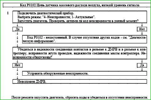
Code P0102 Mass Air Flow Sensor Circuit Low Input

The P0102 code is stored if the TPMSHFM signal period is greater than 850 ms for 0.5 s.
The malfunction indicator comes on during the 3rd trip after a stable malfunction has occurred.
Description of tests
The sequence corresponds to the numbers on the map.
1 Using a scan tool, check whether the P0102 code is active at the time of diagnostics.
Diagnostic information
An intermittent malfunction may be caused by a poor connection, damage to the insulation or core of the wire, or an unreliable connection of the sensor to ground.
It is necessary to ensure that the following are absent faults:
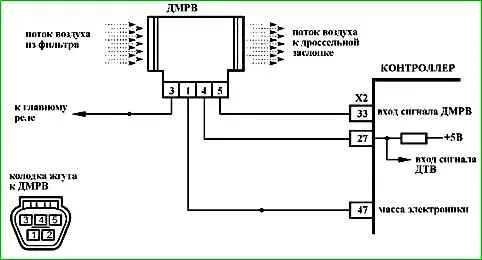
- - Unreliable connection of contacts "X2/33" of the ignition system harness block and controller. Inspect the harness block and controller connector for completeness and correctness of articulation, damage to the locks, presence of damaged contacts and quality of connection of contacts with the wire.
- - Damage to the harness. Check the harness for damage.
- - Clogged air filter in the air intake system. If necessary, replace the filter element.
- - Water or dust getting on the MAF sensor element can also lead to the P0102 code being determined.
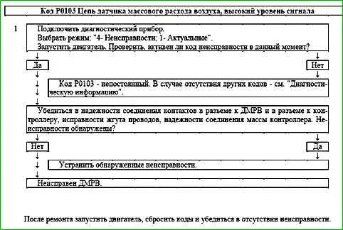
Code P0103 Mass air flow sensor circuit, high signal level

The P0103 code is stored if the TPMSHFM signal period is less than 100 ms for 0.5 s.
The malfunction indicator lights up on the 3rd trip after a stable malfunction has occurred.
Description of tests
The sequence corresponds to the numbers on the map.
1 Using a diagnostic tool, it is checked whether the P0103 code is active at the time of diagnosis.
Diagnostic information
An intermittent malfunction may be caused by poor contact, damage to the insulation or core of the wire, or an unreliable connection of the sensor to ground.
It is necessary to make sure that the following faults are absent:
- - Unreliable connection of contacts "X2/33" of the ignition system harness block and controller. Inspect the harness block and controller connector for completeness and correctness of articulation, damage to the locks, the presence of damaged contacts and the quality of the connection of the contacts to the wire.
- - Damage to the harness. Check harness for damage.
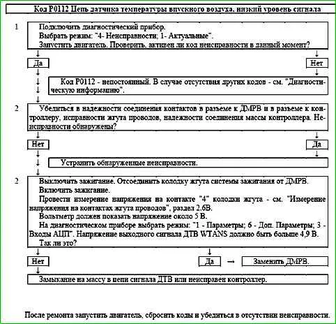
Code P0112 Intake Air Temperature Sensor Circuit Low Voltage

Code P0112 is set if the WTANS sensor signal voltage is less than 0.12 V for 0.2 s.
The malfunction indicator comes on on the 3rd trip after a persistent malfunction has occurred.
Description of tests
The sequence corresponds to the numbers on the map.
- 1 Using the diagnostic tool, it is checked whether the P0112 code is active at the time of diagnostics.
- 2 The integrity of the harness and the serviceability of the input signal circuit are checked.
Diagnostic information
The controller supplies 5 V to the MAF circuit through an internal resistor.
If a malfunction of the air temperature sensor is detected, the controller replaces the sensor readings with a fixed air temperature value (20 °C).
An intermittent malfunction can be caused by damage to the insulation or core of the wire, a short to ground in the input signal circuit.
It is necessary to ensure that there is no damage to the harness.
If the harness connector is not connected to the MAF, then simultaneously with the code P0112 in the controller memory there will be a code P0102.
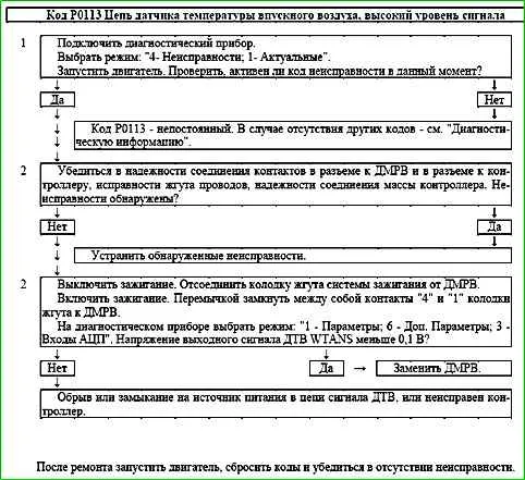
Code P0113 Intake Air Temperature Sensor Circuit, High Voltage

The P0113 code is stored if the following conditions exist:
- - the engine has been running for more than 180 s after starting;
- - the engine is idling (B_LL= "Yes") and the fuel supply is not turned off (B_SA="Off");
- - the WTANS sensor signal voltage is more than 4.88 V for 0.2 s.
The malfunction indicator lights up on the 3rd trip after a persistent malfunction has occurred.
Description of tests
The sequence corresponds to the numbers on the map.
- 1 Using the diagnostic tool, it is checked whether the code is active P0113 during diagnostics.
- 2 The integrity of the harness and the serviceability of the input signal circuit are checked.
Diagnostic information
The controller supplies 5 V to the ITS circuit through an internal resistor.
If a fault in the air temperature sensor is detected, the controller replaces the sensor readings with a fixed air temperature value (20 °C).
An intermittent fault may be caused by poor contact, damage to the wire core, or a short circuit in the ITS signal circuit to the on-board network.
It is necessary to ensure that the following faults are absent:
- - Unreliable connection of contacts "X2/27", "X1/47" of the ignition system harness block and the controller. Inspect the harness block and controller connector for completeness and correctness of articulation, damage to locks, presence of damaged contacts and quality of connection of contacts with the wire.
- - Harness damage. Check harness for damage.
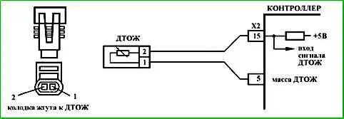
Code P0116 Engine Coolant Temperature Sensor Circuit Out of Range
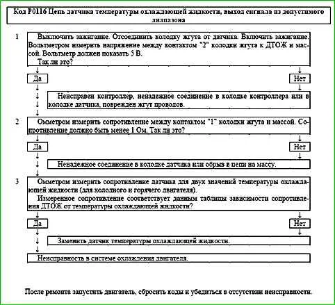
Code P0116 is entered into the controller memory if:
- - the engine is running;
- - the calculated temperature exceeds the measured temperature by the threshold value.
The malfunction indicator lights up on the 3rd trip after a stable malfunction has occurred.
Description of tests
The sequence corresponds to the numbers on the map.
- 1 The sensor output signal circuit is checked for serviceability.
- 2 The sensor ground circuit is checked for serviceability.
- 3 The sensor resistance is measured and the cause of the code is determined - a malfunction of the sensor or cooling system engine.
Diagnostic information
The controller supplies 5 V to the coolant temperature sensor circuit through an internal resistor.
If a coolant temperature sensor malfunction is detected, the controller calculates the coolant temperature using a special algorithm.
It is necessary to check the sensor grounding circuit for faulty wiring or connections. Check the sensor contacts for secure connections.
It is necessary to check the sensor resistance for compliance with the nominal value.
A malfunction in the engine cooling system (open thermostat, etc.) can cause the P0116 code to appear.
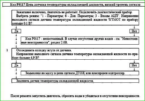
Code P0117 Engine Coolant Temperature Sensor Circuit Low Voltage

Code P0117 is entered into the controller memory if the WTMOT sensor signal voltage is less than 0.1 B.
The malfunction indicator lights up 2 drive cycles after the malfunction code has occurred.
Description of checks
1 The presence of a short to ground in the sensor signal circuit is determined.
Diagnostic information
The controller supplies 5 V to the coolant temperature sensor circuit through an internal resistor.
When a coolant temperature sensor malfunction is detected, the controller calculates the coolant temperature using a special algorithm.
It is necessary to check the sensor signal circuit for faulty wiring and a short to ground.
An intermittent malfunction may be caused by engine overheating above +130 °C.
Code P0118 Engine Coolant Temperature Sensor Circuit High Voltage

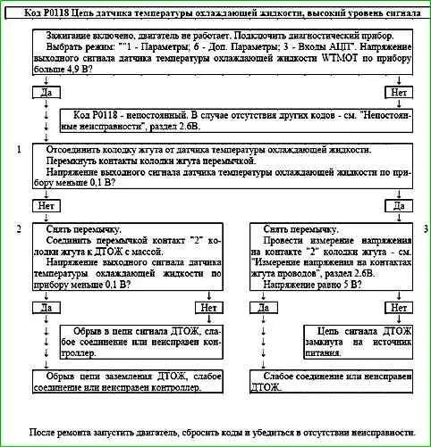
Code P0118 is entered to the controller memory if the WTMOT sensor signal voltage is more than 4.9 V.
The malfunction indicator lights up 2 drive cycles after the malfunction code has occurred.
Test Description
- 1 This test simulates the conditions for the P0117 code - high temperature/low resistance of the sensor.
If the controller receives a low voltage signal (high temperature), and the scan tool shows 135 ° C or higher, then the controller and the coolant temperature sensor circuit are OK.
- 2 The sensor signal circuit is checked for an open.
- 3 With the sensor disconnected, the voltage between contacts "1" and "2" of the harness connector to the coolant temperature sensor should be about 5 V.
Diagnostic Information
The controller sends voltage to the coolant temperature sensor circuit 5 V via an internal resistor.
When a coolant temperature sensor malfunction is detected, the controller calculates the coolant temperature using a special algorithm.
It is necessary to check the grounding circuit of the sensors for faulty wiring or connections. Check the sensor contacts for poor connections
Code P0122 Throttle Position Sensor A Circuit Low Input
Code P0122 is set if:
- - ignition is on;
- - throttle position sensor UDKP1 signal voltage is less than 0.25 V for 0.12 s.
The malfunction indicator lights up 5 s after the malfunction code has occurred.
Description of tests
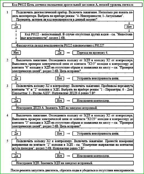
The sequence corresponds to the numbers on the map.
- 1 - Using the diagnostic tool, it is checked whether the P0122 code is active at the time of diagnostics. If only the P0122 code is recorded, then the fault must be looked for in the signal circuit of the TPS A.
If the P0122 and P0222 codes are recorded simultaneously, then the fault must be looked for in the power supply circuit of the TPS A and TPS B.
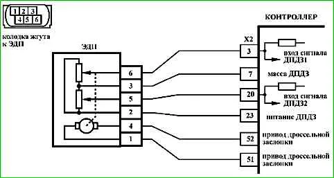
- 2 - The circuit from contact "X2/3" of the controller to contact "6" of the EDS is checked.
- 3 - The controller is checked: when contacts "6" and "2" of the connector to the EDS are short-circuited using a tester, the TPS A signal on the diagnostic tool should change.
- 4 - The circuit from contact "X2/23" of the controller to contact "2" of the EDS is checked.
- 5 - The controller is checked: a reference voltage of 5 V with controller.
Diagnostic information
If a malfunction of the TPS A circuit is detected, the engine management system will operate in emergency mode until the end of the current trip.
The following emergency modes are possible:
- - engine power limitation if the the TPS B circuit is correct;
- - de-energize the throttle actuator and limit engine speed (2500 rpm), if the TPS A and TPS B circuits are faulty.
The diagnostic tool in the "1 - Parameters; 6 - Additional Parameters; 3 - ADC Inputs" mode displays the TPS A (UDKP1) and TPS B (UDKP2) signals in volts.
When the throttle valve opens, the TPS A signal increases, the TPS B signal decreases.
When the throttle valve is fully closed, the TPS A signal should be in the range of 0.3 ... 0.6 V, the TPS B signal should be in the range of 4.4 ... 4.7 V.
The sum of the TPS A and TPS B signals should be equal to (5±0.1) V at any throttle position.
If the ECM or ECU controller is replaced, or the controller is reset using the diagnostic tool (mode "5 - Additional tests; 1 - ECU reset with initialization"), it is necessary to perform the throttle zero adaptation procedure.
To do this, with the vehicle stationary, turn on the ignition, wait 30 s, turn off the ignition, wait for the main relay to disconnect.
Adaptation will be interrupted if:
- - the engine is cranking;
- - the vehicle is moving;
- - the accelerator pedal is pressed;
- - the engine temperature is below 5 °C or above 100 °C;
- - the ambient air temperature is below 5 °C.
If The electric throttle actuator is de-energized, the throttle valve is held in the limp home position (7-8%) by the forward and return springs.
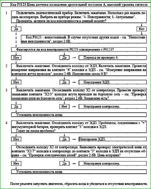
Code P0123 Throttle Position Sensor A Circuit High Voltage

Code P0123 is entered if:
- - ignition is on;
- - throttle position sensor UDKP1 signal voltage is more than 4.75 V for 0.12 s.
The malfunction indicator lights up 5 s after the malfunction code has occurred.
Description of tests
The sequence corresponds to the numbers on the map.
- 1 - Using the diagnostic tool, it is checked whether the code is active P0123 during diagnostics. If only the P0123 code is recorded, then the fault must be looked for in the TPS A signal circuit. If the P0123 and P0223 codes are recorded simultaneously, then the fault must be looked for in the TPS A and TPS B ground circuits.
- 2 - A voltage check is performed in the TPS A signal circuit with the sensor disconnected. Voltage should be around 0 V.
- 3 - The signal circuit is checked for a short to power.
- 4 - The ground circuit of TPS A and TPS B is checked.
Diagnostic information
If a fault in the TPS A circuit is detected, the engine management system will operate in emergency mode until the end of the current trip.
The following emergency modes are possible:
- - engine power limitation if the TPS B circuit is intact;
- - throttle actuator power is cut off and engine speed is limited (2500 rpm) if the TPS A and TPS B circuits are faulty.
The diagnostic tool is in mode "1 - Parameters; 6 - Additional Parameters; 3 - Inputs The ADC" shows the signals of TPS A (UDKP1) and TPS B (UDKP2) in volts.
When the throttle valve is opened, the TPS A signal increases, the TPS B signal decreases.
When the throttle valve is fully closed, the TPS A signal should be in the range of 0.3-0.6 V, the TPS B signal should be in the range of 4.4-4.7 V.
The sum of the TPS A and TPS B signals should be equal to (5±0.1) V at any throttle position.
In case of replacing the ECM or the ECM controller, or resetting the controller using the diagnostic tool (mode "5 - Additional tests; 1 - ECU reset with initialization"), it is necessary to perform the throttle zero adaptation procedure.
To do this, turn on the ignition with the vehicle stationary, wait 30 seconds, turn off the ignition, wait for the main relay to disconnect.
Adaptation will be interrupted if:
- - the engine is cranking;
- - the vehicle is moving;
- - the accelerator pedal is pressed;
- - the engine temperature is below 5 °C or above 100 °C;
- - the ambient air temperature is below 5 °C.
If the throttle actuator is de-energized, the throttle valve is held in the Limp home position (7-8%) by means of the direct and return springs.
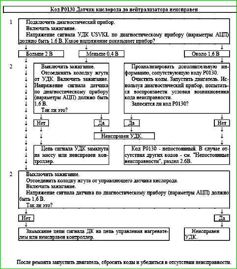
Code P0130 Pre-catalyst oxygen sensor faulty
Code P0130 is set if:
- - the engine has been running for a time sufficient to warm up the oxygen sensor (up to 10 minutes, determined by the coolant temperature at start);
- - the UDC signal repeats the shape of the heater control signal (shorting the output signal circuit to the heater control circuit);
or the voltage of the warmed-up UDC signal (parameter USVKL) is in the range from 0.6 to 1.5 V, and the voltage of the DDC signal (parameter USHKL) is less than 0.1 V, while the system supplies fuel in the feedback mode according to the UDC signal (B_LR="Yes");
or the voltage of the warmed-up UDC signal (parameter USVKL) is in the range from 60 to 400 mV, and the voltage of the DDC signal (parameter USHKL) is greater than 0.5 V, while the system supplies fuel in the feedback mode according to the UDC signal (B_LR="Yes").
The malfunction indicator lights up on the 3rd trip after the occurrence of a stable malfunctions.
Description of tests
The sequence corresponds to the numbers on the map.
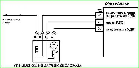
- 1 - The value of the signal voltage of the control oxygen sensor is checked using a diagnostic tool.
- 2 - The serviceability of the sensor signal circuit is checked.
Diagnostic information
The voltage at the "A" terminal of a cold oxygen sensor is 1.6 V. For a warmed-up sensor, the voltage during closed-loop operation changes in the range of 50-900 mV.
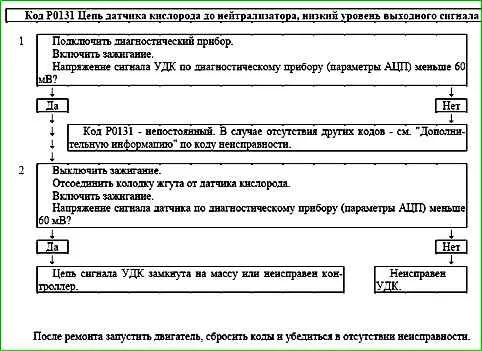
Code P0131 Pre-catalyst oxygen sensor circuit, low output

Code P0131 is set if:
- - the engine has been running for a time sufficient to warm up the oxygen sensor (up to 10 minutes, determined by the coolant temperature at start-up);
- - voltage cold control oxygen sensor signal USVKL is below 60 mV for 5 s;
or for 10 seconds the voltage of the warm UDC signal (parameter USVKL) is less than 60 mV, and the voltage of the HKD signal (parameter USHKL) is greater than 0.5 V, while the system supplies fuel in the feedback mode according to the UDC signal (V_LR="Yes").
The malfunction indicator lights up on the 3rd trip after a persistent malfunction occurs.
Description of tests
The sequence corresponds to the numbers on the map.
- 1 - The value of the control oxygen sensor signal voltage is checked using a diagnostic tool.
- 2 - The serviceability of the sensor signal circuit is checked.
Diagnostic information
Voltage at terminal "A" of a cold oxygen sensor is 1.6 V. For a warmed-up sensor, the voltage during closed-loop operation varies in the range of 50-900 mV.
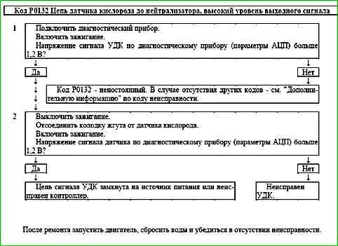
Code P0132 Pre-catalyst Heated Oxygen Sensor Circuit, High Output

Code P0132 is recorded if:
- - the engine has been running for a period sufficient to warm up the oxygen sensor (up to 10 minutes, determined by the coolant temperature at start);
- - the voltage of the signal from the control oxygen sensor USVKL is higher than 1.2 V for 5 s.
The malfunction indicator lights up on the 3rd trip after a persistent malfunction has occurred.
Description of tests
The sequence corresponds to the numbers on the map.
- 1 - The value of the oxygen sensor control signal voltage is checked using a diagnostic tool.
- 2 - The sensor signal circuit is checked for serviceability.
Diagnostic information
The voltage at contact "A" of a cold oxygen sensor is 1.6 V. For a warmed-up sensor, the voltage when operating in a closed circuit changes in the range of 50-900 mV.
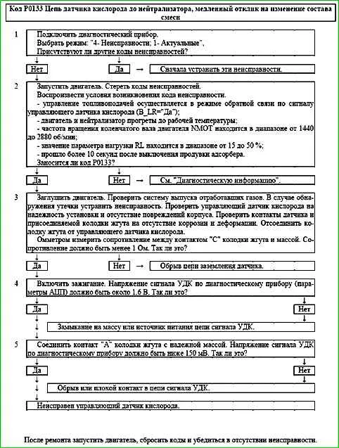
Code P0133 Pre-catalyst HO2S Circuit Slow Response

Code P0133 is set if:
- - the period of the UDC DTPSVKMF signal is more than 2 seconds;
- - there are no fault codes P0030, P0031, P0032, P0441, P0444, P0458, P0459, P0560, P0562, P0563;
- - fuel supply is controlled in the feedback mode by the signal from the control oxygen sensor (B_LR="Yes");
- - the catalytic converter has warmed up to operating temperature;
- - the NMOT engine crankshaft speed is in the range from 1440 to 2880 rpm;
- - the RL load parameter value is in the range from 15 to 50%;
- - more than 10 seconds have passed since the purge of the adsorber was turned off.
The malfunction indicator lights up on the 3rd trip after a persistent malfunction has occurred.
Description of tests
The sequence corresponds to the numbers on the map.
- Checks for other malfunctions.
- Checks for a permanent malfunction.
- Checks for the possibility of the code occurring due to a malfunction in the exhaust system or a contact failure, checks the sensor ground circuit.
- Checks the serviceability of the sensor output signal circuit.
- Checks the serviceability of the sensor output signal circuit.
Diagnostic information
An intermittent malfunction may be caused by the presence of the following malfunctions:
Incorrect or unreliable connection of ignition system harness pad contacts, sensor and controller. Inspect sensor and controller connectors, harness pads for completeness and correctness of articulation, damage to locks, presence of damaged contacts and quality of contact connection to wire.
Harness damage. Check the harness for damage.
Code P0134 The oxygen sensor circuit to the converter is inactive

Code P0134 is recorded if:
- - the engine has been running for a period of time sufficient to warm up the oxygen sensor (up to 10 minutes, determined by the coolant temperature at start-up);
- - the oxygen sensor signal voltage USVKL was in the range of 1.2...1.6 V for 5 s.
The malfunction indicator lights up on the 3rd trip after a persistent malfunction has occurred.
Description of tests
The sequence corresponds to the numbers on the map.
- 1 If the voltage is within the specified limits, then the oxygen sensor has not warmed up or the sensor output signal circuit is faulty.
- 2 The serviceability of the input signal circuit is checked sensor by measuring the voltage between terminal "A" of the harness connector and ground.
Diagnostic information
The voltage at terminal "A" of a cold oxygen sensor is 1.6 V.
For a warmed-up sensor, the voltage during closed-loop operation changes in the range of 50...900 mV.
The cause of the P0134 code may be:
- - insufficient power of the oxygen sensor heater;
- - installation of a different type of oxygen sensor;
- - unreliable contact in the harness and sensor connectors.
If the following is recorded simultaneously with the P0134 code:
- code P0030, then the probable cause of the malfunction is the disconnection of the oxygen sensor connector from the wiring harness and troubleshooting should begin with the code chart P0030.

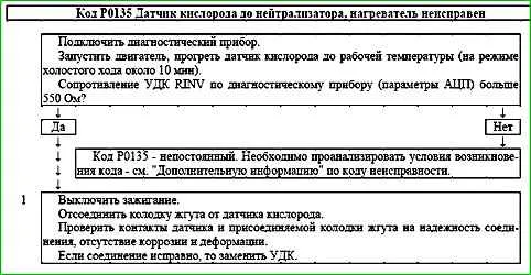
Code P0135 is set if:
- - the engine is running;
- - the temperature of the neutralizer calculated by the controller is above the threshold;
- - the resistance of the UDC calculated by the controller is above the threshold.
The malfunction indicator lights up on the 3rd trip after a persistent malfunction has occurred.
Description of checks
The sequence corresponds to the numbers on the map.
- The reliability of the connection of the oxygen sensor to the wiring harness is checked.
Diagnostic information
During operation, the controller calculates the resistance of the sensitive element of the UDC, which depends on the operating temperature of the sensor.
This, in turn, is determined by the temperature of its heater and exhaust gases.
Depending on the engine operating mode, the resistance of the oxygen sensor can vary in the range of 90...550 Ohm.
If at the same time with the code P0135 the code P0030 is recorded, then troubleshooting should begin with the code map P0030.
The cause of the code P0135 may be:
- - installation of a different type of oxygen sensor;
- - unreliable contact in the harness and sensor pads.
