The controller is the central device of the engine management system
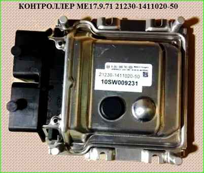
It receives information from sensors and controls actuators, ensuring optimal engine operation at a given level of vehicle performance
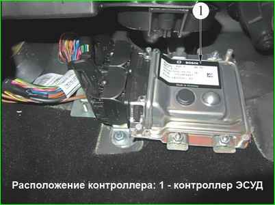
The controller is located in the passenger footwell and is attached to the front panel (Fig. 2).
The controller controls actuators such as fuel injectors, an electric throttle body, an ignition coil, an oxygen sensor heater, an adsorber purge valve and various relays.
The controller controls the switching on and off of the main relay (ignition relay), through which the supply voltage from the battery is supplied to the system components (except for the electric fuel pump, electric fan, control unit and APS status indicator).
The controller switches on the main relay when the ignition is switched on.
When the ignition is switched off, the controller delays the switching off of the main relay for the time required to prepare for the next switching on (completion of calculations, setting the throttle valve to the position preceding the start engine).
When the ignition is turned on, the controller, in addition to performing the above-mentioned functions, exchanges information with the APS (if the immobilization function is enabled).
If the exchange determines that access to the vehicle is permitted, the controller continues to perform engine control functions. Otherwise, the engine operation is blocked.
The controller also performs the function of diagnosing the system.
It detects the presence of faults in the system elements, turns on the alarm and stores codes in its memory that indicate the nature of the fault and help the mechanic to carry out repairs.
The controller is a complex electronic device, the repair of which should only be carried out at the manufacturer.
During the operation and maintenance of the car, disassembling the controller is prohibited.
Unauthorized modification of the controller software can lead to deterioration in the performance characteristics of the engine and even to its breakdown.
In this case, the warranty obligations of the car manufacturer for the maintenance and repair of the engine and control system are lost.
The controller supplies a supply voltage of 5 or 12 V to various devices.
In some cases, it is supplied through controller resistors with such a high nominal resistance that when when the control lamp is connected to the circuit, it does not light.
In most cases, a conventional voltmeter with low internal resistance does not give accurate readings.
To monitor the voltage of the controller output signals, a digital voltmeter with an internal resistance of at least 10 MOhm is required.
Controller Memory
The controller has three types of memory: programmable read-only memory (ROM), random access memory (RAM), and electrically reprogrammable memory (ERPROM).
Read-only memory (ROM)
The ROM stores the control program, which contains a sequence of operating commands and calibration information.
Calibration information is the control data for injection, ignition, idle speed, etc., which in turn depend on the weight of the car, the type and power of the engine, the gear ratios transmission and other factors.
This memory is non-volatile, i.e. its contents are retained when the power is turned off.
Random Access Memory (RAM)
Random Access Memory is used by the microprocessor for temporary storage of measured parameters, calculation results, and fault codes.
The microprocessor can write data to RAM or read it as needed.
This memory is volatile.
When the power supply is interrupted (disconnecting the battery or disconnecting the wiring harness from the controller), the diagnostic fault codes and calculation data contained in RAM are erased.
Electrically Reprogrammable Memory (ERPROM)
ERPROM is used to store controller, engine, and vehicle identifiers, as well as vehicle anti-theft alarm system (ATS) password codes.
Password codes, received by the controller from the APS control unit, are compared with those stored in the EPROM and the microprocessor changes rum according to a certain law. Article - On-board diagnostics and fault codes of the Niva Chevrolet ECU with the ME17.9.71 controller
The EEPROM is a non-volatile memory, its contents are saved when the power is turned off.
Replacing the controller
To prevent damage to the controller, when disconnecting the wire from the negative terminal of the battery or the wiring harness from the controller, the ignition must be off.
Removing the controller
Turn off the ignition.
Disconnect the wire from the negative terminal of the battery.
Unscrew the nuts securing the controller and remove the controller, disconnecting the wiring harness pads from it.
Disconnect the pads from the controller only on a removed controller.
If the controller is faulty, use "clean" controller
Installing the controller
Connect the wiring harness connectors to the controller.
Install the controller on the vehicle.
Connect the wire to the negative terminal of the battery.
Checking the functionality of the controller
After replacing the controller or resetting the controller using a diagnostic device (mode "5 - Additional tests; 1 - ECU reset with initialization") it is necessary to perform the throttle valve zero adaptation procedure and the misfire diagnostics function adaptation procedure.
Throttle valve zero adaptation procedure:
- with the vehicle stationary, turn on the ignition, wait 30 s, turn off the ignition, wait for the main relay to disconnect.
Adaptation will be interrupted if:
- - the engine is cranking;
- - the vehicle is moving;
- - the accelerator pedal is pressed;
- - the engine temperature is below 5 °C or above 100 °C;
- - the ambient air temperature is below 5 °C.
Misfire diagnostics function adaptation procedure:
- - warm up the engine to operating temperature (controlled parameter TMOT_W = 60...90 °C);
- - accelerate the car in 2nd gear until reaching increased crankshaft speed (NMOT_W = 4000 min -1) and perform engine braking (NMOT_W = 1000 min -1);
- - perform engine braking six times during one trip.
Carry out diagnostics (see. order in chart A "Checking the diagnostic circuit").
Assignment of contacts of the ME17.9.71 21230-1411020-50 controller
contact - circuit
Connector X1
- 1 Not used.
- 2 Not used.
- 3 Ground of the refrigerant pressure sensor. The voltage on the contact should be zero.
- 4 Ground of analog sensors. Not used.
- 5 Accelerator pedal sensor 1 ground. The voltage at the terminal should be zero.
- 6 Accelerator pedal sensor 2 ground. The voltage at the terminal should be zero.
- 7 Not used.
- 8 Not used.
- 9 Not used.
- 10 Input. Refrigerant pressure sensor. The signal from the pressure sensor is directly proportional to the pressure applied to it, and changes linearly within the range from 0.25 V to 3.35 V when the pressure changes from 100 kPa to 2400 kPa.
- 11 Accelerator pedal sensor 2. When the accelerator pedal is released, the signal should be within the range of 0.23 ... 0.38 V. When the accelerator pedal is pressed, the signal increases to 1.40 ... 1.55 V.
- 12 Not used.
- 13 Not used.
- 14 Analog sensor ground. Not used.
- 15 Output. Main relay. The supply voltage is supplied to the relay coil from the positive terminal of the battery.
The control signal is discrete, the active level is low, no more than 1.5 V. When the ignition switch is moved from the "off" position to the "on" position, the relay should turn on immediately.
When the ignition switch is moved from the "on" position to the "off" position, the controller delays the main relay from turning off for about 10 seconds.
- 16 Input. Terminal "15" of the ignition switch. The nominal voltage with the ignition on and the engine off is 12 V. With the engine running - 13.5-14.5 V.
- 17 Not used.
- 18 Not used.
- 19 Not used.
- 20 Not used.
- 21 Accelerator pedal sensor 1. When the accelerator pedal is released, the signal should be within 0.46 ... 0.76 V. When the accelerator pedal is pressed, the signal increases to 2.80 ... 3.10 V.
- 22 Not used.
- 23 Not used.
- 24 Not used.
- 25 5 V supply for the refrigerant pressure sensor. A stabilized voltage of 5 V is supplied to the contact.
- 26 5 V power supply for accelerator pedal position sensor 2. A stabilized voltage of 5 V is supplied to the contact.
- 27 LIN bus. Not used.
- 28 Crankshaft speed signal output to the tachometer. The active signal level is low, no more than 1 V.
The high level voltage of the signal is equal to about the vehicle's on-board network voltage. The pulse repetition rate is equal to twice the engine crankshaft speed. The duty cycle at the active level is 33%.
- 29 Fuel consumption signal output to the trip computer. Not used.
- 30 Not used.
- 31 Air conditioner relay control output. The control signal is discrete, the active level is low, no more than 1 V, issued when the air conditioner is allowed to turn on.
- 32 Not used.
- 33 Not used.
- 34 Input of the signal for requesting the air conditioner to turn on. In the absence of a request signal, this contact is connected to ground through the internal resistor of the controller. When the air conditioner switch is turned on, the contact is supplied with voltage from the on-board network.
- 35 Input. Switch 1 of the brake pedal. When the brake pedal is released, the contact has voltage from the vehicle's electrical system from terminal "15" of the ignition switch.
- 36 Input. Clutch pedal switch. When the clutch pedal is released, the contact has voltage from the vehicle's electrical system from terminal "15" of the ignition switch.
- 37 5 V supply. Not used.
- 38 5 V supply for accelerator pedal position sensor 1. A stabilized voltage of 5 V is supplied to the contact.
- 39 Input/output K-line. Through this contact, the controller exchanges data with the APS control unit and external diagnostic equipment.
The data is transmitted as a pulsed change in voltage from a high level (at least 0.8 of the on-board voltage) to a low level (not more than 0.2 of the on-board voltage).
The data exchange session with the APS begins after the ignition is turned on.
If, as a result, the APS is disarmed, the controller enters the normal mode of performing all engine control functions and exchanging data with the diagnostic equipment.
Otherwise, the controller prohibits engine operation and performs only external diagnostic support functions.
- 40 Output. MIL indicator lamp. The power supply voltage of the indicator comes from terminal "15" of the ignition switch.
When the ignition is turned on without starting the engine, as well as in the presence of malfunctions, the signal has a low voltage level - no more than 2 V. In the absence of malfunctions, the contact has voltage from the on-board network.
- 41 Output control of relay 1 of the engine cooling system fan - reduced performance.
The supply voltage of the fan relay winding comes from the output (terminal "87") of the main relay.
The control signal is discrete, the active level is low, no more than 1 V. The controller turns on the relay when the coolant temperature is above 99 ° C, as well as if there are coolant temperature sensor fault codes in the controller memory or when the air conditioner is running.
- 42 Output control of the electric fuel pump relay. The supply voltage of the electric fuel pump relay winding comes from the output (terminal "87") of the main relay.
The control signal is discrete, the active level is low, no more than 1 V, it is issued when fuel supply is enabled.
- 43 Not used.
- 44 Not used.
- 45 Not used.
- 46 Not used.
- 47 Input. Brake pedal switch 2. When the brake pedal is pressed, the contact has voltage from the on-board network from terminal "30" of the ignition switch.
- 48 Not used.
- 49 Not used.
- 50 Not used.
- 51 Control output of the additional starter relay. The supply voltage of the additional starter relay winding comes from terminal "15" of the ignition switch.
The control signal is discrete, the active level is low, no more than 1 V. When the control signal is received, the additional relay turns on and connects terminal "50" of the ignition switch to terminal "50" of the starter solenoid relay.
- 52 Control output of relay 2 of the engine cooling system fan - maximum performance.
The supply voltage of the fan relay winding comes from the output (terminal "87") of the main relay. The control signal is discrete, the active level is low, no more than 1 V.
The controller turns on the relay when the coolant temperature is above 101 °C, as well as at high refrigerant pressure in the line, both with the air conditioner running and without it
- 53 Ground of output stages. Used to connect the mass of the output keys for controlling actuators to the vehicle body.
- 54 Mass of output stages. Used to connect the mass of the output keys for controlling actuators to the vehicle body.
- 55 Input of the on-board network voltage at the output of the main relay.
The voltage from the output of the main relay (terminal "87") with the engine not running (for an unlimited time after turning on the ignition without starting the engine, as well as for 10 seconds after turning off the ignition) is 12 V. With the engine running - 13.5-14.5 V.
- 56 Input voltage of the on-board network at the output of the main relay.
The voltage from the output of the main relay (terminal "87") with the engine off (for an unlimited time after turning on the ignition without starting the engine, as well as for 10 seconds after turning off the ignition) is 12 V. With the engine running - 13.5-14.5 V.
Connector X2
- 1 Crankshaft position sensor signal input (contact "B"). When the engine crankshaft rotates, an alternating current voltage signal close in shape to a sine wave is present at the contact. The frequency and amplitude of the signal are proportional to the crankshaft speed.
- 2 Diagnostic oxygen sensor signal input. If the oxygen sensor temperature is below 150 °C (not warmed up), there is a voltage of 1.6 V at the contact.
When the oxygen sensor is warmed up, then when operating in feedback mode and with a serviceable neutralizer in steady-state mode, the voltage should change in the range of 590 ... 750 mV.
- 3 Input. Throttle position sensor 1. When the ignition is on, there should be a DC voltage signal at the input, the value of which depends on the degree of opening of the throttle valve: with a fully closed valve 0.3 ... 0.6 V.
- 4 Ground of the control oxygen sensor. The voltage at the contact should be zero.
- 5 Ground of the coolant temperature sensor. The voltage at the contact should be zero.
- 6 Ground of the diagnostic oxygen sensor. The voltage at the contact should be zero.
- 7 Ground of the throttle position sensors. The voltage at the contact should be zero.
- 8 Ground of the analog sensors. Not used.
- 9 Not used.
- 10 Power supply 5 V. Not used.
- 11 Not used.
- 12 Not used.
- 13 Crankshaft position sensor signal input (contact "A"). When the engine crankshaft rotates, an AC voltage signal close to a sine wave is present at the contact. The frequency and amplitude of the signal are proportional to the crankshaft rotation frequency.
- 14 Not used.
- 15 Coolant temperature sensor signal input. The voltage at the contact depends on the coolant temperature: at a temperature of 27 °C, the voltage is about 2.4 V. If the sensor circuit is open, the voltage at the contact is 5 ± 0.1 V.
- 16 Not used.
- 17 Not used.
- 18 Not used.
- 19 Not used.
- 20 Input. Throttle position sensor 2. When the ignition is on, there should be a DC voltage signal at the input, the value of which depends on the degree of opening of the throttle valve: with the valve fully closed 4.4 ... 4.7 V.
- 21 Not used.
- 22 Not used.
- 23 5 V power supply for throttle position sensors. A stabilized voltage of 5 V is supplied to the contact.
- 24 Not used.
- 25 Not used.
- 26 Not used.
- 27 Input. Intake air temperature sensor. The voltage on the contact depends on the temperature of the air entering the engine: at a temperature of 33 °C, the voltage is about 1.8 V. If the sensor circuit is open, the voltage on the contact is 5±0.1 V.
- 28 Not used.
- 29 Not used.
- 30 Input of the control oxygen sensor signal. If the oxygen sensor temperature is below 150 °C (not warmed up), there is a voltage of 1.6 V at the contact.
When the oxygen sensor is warmed up, then with the engine running in closed loop mode, the voltage switches several times per second between a low value of 50-100 mV and a high value of 800...900 mV.
- 31 Phase sensor signal input. In the absence of a signal, the on-board voltage is supplied to this contact through the internal resistor of the controller.
The sensor pulses the circuit to ground once per revolution of the camshaft, which allows for recognition of the firing order of the engine cylinders.
- 32 Vehicle speed sensor signal input. The voltage of the on-board network is supplied to this contact via the internal resistor of the controller.
When the car is moving, the sensor pulses the circuit to ground with a frequency proportional to the speed of the car (6 pulses per meter of travel).
- 33 Mass air flow sensor signal input. Digital signal with a frequency dependence on the amount of air passing through the MAF (the frequency increases with increasing air flow).
- 34 Not used.
- 35 Canister purge valve control output. The supply voltage of the purge valve of the adsorber comes from the output (terminal "87") of the main relay.
The control signal is pulsed, the active level is low, no more than 1 V. The duty cycle changes depending on the engine operating mode in the range of 0...100%.
- 36 Not used.
- 37 Input 1 of the knock sensor signal. The signal is an alternating current voltage, the amplitude and frequency of which depend on vibrations of the engine cylinder block.
- 38 Input 2 of the knock sensor signal. The signal is an alternating current voltage, the amplitude and frequency of which depend on the vibrations of the engine cylinder block.
- 39 Output control of the diagnostic oxygen sensor heater. The supply voltage of the oxygen sensor heater comes from the output (terminal "87") of the main relay.
The control signal is pulsed, the active level is low, no more than 2 V. The duty cycle changes in the range of 0 ... 100% depending on the temperature and humidity in the area of the sensor installation.
- 40 Not used.
- 41 Not used.
- 42 Output control of the injector 2 cylinder. The supply voltage of the injector winding comes from the output (terminal "87") of the main relay.
The control signal is pulsed, the active level is low, no more than 1.5 V. The duration depends on the engine operating mode and ranges from several to tens of milliseconds.
- 43 Output for control of the 3rd cylinder injector. The supply voltage of the injector winding comes from the output (terminal "87") of the main relay.
The control signal is pulsed, the active level is low, no more than 1.5 V. The duration depends on the engine operating mode and ranges from several to tens of milliseconds.
- 44 Output for control of the 1st cylinder injector. The supply voltage of the injector winding comes from the output (terminal "87") of the main relay.
The control signal is pulsed, the active level is low, no more than 1.5 V. The duration depends on the engine operating mode and ranges from several to tens of milliseconds.
- 45 Output for controlling the 4th cylinder injector. The supply voltage of the injector winding comes from the output (terminal "87") of the main relay.
The control signal is pulsed, the active level is low, no more than 1.5 V. The duration depends on the engine operating mode and ranges from several to tens of milliseconds.
- 46 Output for controlling the heater of the control oxygen sensor. The supply voltage of the oxygen sensor heater comes from the output (terminal "87") of the main relay.
The control signal is pulsed, the active level is low, no more than 2 V. The duty cycle varies in the range of 0 ... 100% depending on the temperature and humidity in the sensor installation area.
- 47 Sensor ground. The voltage on the contact should be zero.
- 48 Not used.
- 49 Not used.
- 50 Ground of output stages. Used to connect the ground of the output keys for controlling actuators to the car body.
- 51 Output. Throttle actuator "+" (contact "1").
- 52 Output. Throttle actuator "-" (contact "4").
- 53 Not used.
- 54 Output for controlling the primary winding of the ignition coil of cylinders 2-3. The supply voltage of the primary winding of the ignition coil comes from terminal "15" of the ignition switch.
The control signal is pulsed, the active level is low, no more than 2.5 V. The duration depends on the voltage of the on-board network - from several to tens of milliseconds.
- 55 Not used.
- 56 Output for controlling the primary winding of the ignition coil of cylinders 1-4. The supply voltage of the primary winding of the ignition coil comes from terminal "15" of the ignition switch.
The control signal is pulsed, the active level is low, no more than 2.5 V. The duration depends on the voltage of the on-board network - from several to tens of milliseconds.
")

")
")
")
")
")
")
")