Front wheel brake mechanism (Fig. 1) disc with floating three-piston caliper
Cylinder block 1 is secured in the caliper on two guides and fixed with a spring retainer.
Brake pads 2 with steel bases having a figured shape, ensuring their tight fit to the pad guide.
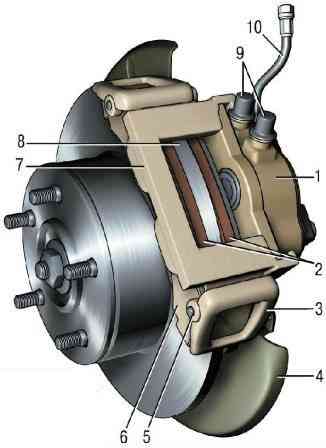
When installing the pads, spring-loaded levers 3 press the caliper 7 to the ends of the pads, which ensures constant pressure of the pads to the grooves of the guide.
The brake disc 8 is made of cast iron.
Replacing the brake pads of the front brake mechanism
The minimum permissible thickness of the friction linings of the brake pads is 1.5 mm. Replace the pads in the following cases:
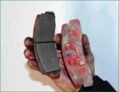
- – the thickness of the linings is less than 1.5 mm;
- – the surface of the linings is oily;
- – the linings are not firmly connected to the base;
- – the linings have deep grooves and chips.
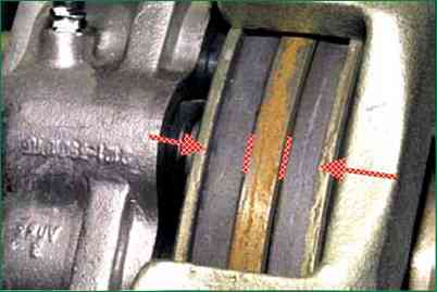
If for some reason you removed the front wheel, check the condition of the pads through the hole in the brake caliper housing.
If the thickness of the friction linings is about 2 mm, replace the pads.
If the car pulls to the side when braking or you hear extraneous noise, remove the brake pads and check their condition.
You will need: a jack, wheel chocks, a screwdriver, pliers, a punch, wire brush, hammer.
Only loosen and tighten the wheel nuts with the vehicle on the ground. Do not use gasoline, diesel fuel or any other mineral solvents to clean the brakes.
The brake pads must be replaced in the brake mechanisms of both front wheels at the same time.
It is not allowed to replace the inner and outer pads between each other, as well as between the left and right wheels. This can lead to uneven braking.
Brake the vehicle with the parking brake and install wheel chocks under the rear wheels.
Remove the front wheel.
Clean the brake mechanism from dirt. To facilitate disassembly, apply a liquid such as WD-40 to the places where the pins are connected to the caliper and the pressure levers.
Pump out some of the fluid from the reservoir if the brake fluid level in the reservoir is at or near the "MAX" mark before replacing the pads.
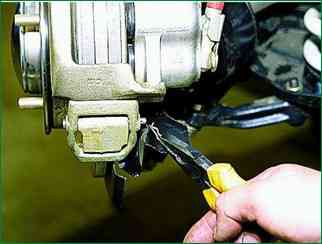
Use pliers to remove the cotter pin of the lower axis of the pressure lever.
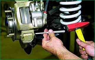
Using a punch, we knock off the axis of the pressure lever
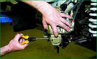
Holding the lever, we take out the axle with pliers.
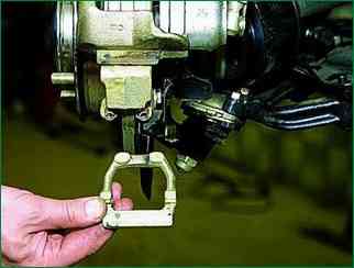
Remove the pressure lever.
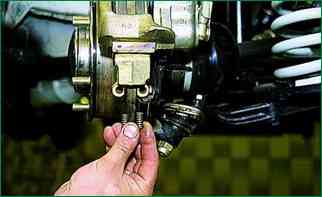
We take out two springs of the pressure lever from the guide of the shoes so as not to lose them.
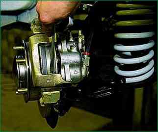
Prying with a screwdriver, we lift the brake caliper and put it on the steering knuckle.
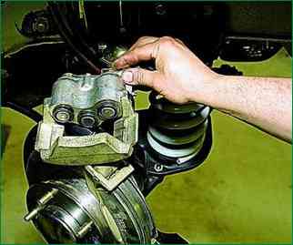
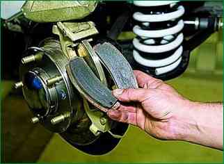
We remove the brake pads.
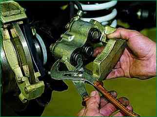
Before installing new brake pads, it is necessary to move the pistons as far as possible into the cylinders.
Using sliding pliers (or a gas wrench), press the pistons into the cylinders.
You can also press the pistons into the cylinders in another way.
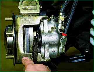
To do this, insert the outer shoe into the guide and, having installed the caliper in place, press the pistons into the cylinders with a mounting blade.
Then assemble the unit in the reverse order.
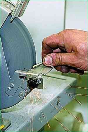
To make it easier to install the clamping lever axle, sharpen its tip on a grinder to form a cone.
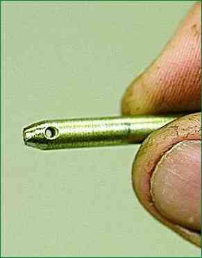
Before installing, lubricate the clamping lever axle with graphite grease
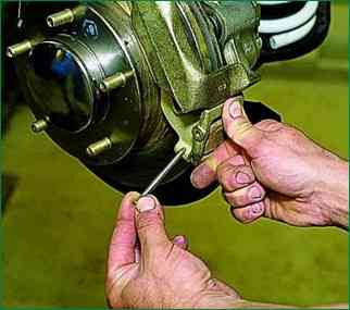
Pressing the lever, insert the axle.
After installing the brake pads, you need to press the brake pedal several times so that the pistons of the cylinders bring the pads to the brake disc.
Check the brake fluid level in the reservoir and top up to normal if necessary.
After replacing worn brake pads with new ones, do not rush to immediately drive onto busy highways.
It is possible that during the first intensive braking, you will be unpleasantly surprised by the low efficiency of the brakes, although the pads were installed branded.
Brake discs also wear out, and new pads only touch them with their edges, practically without braking.
Choose a quiet street or a driveway without cars and brake smoothly several times so that the pads rub in and begin to fit with their entire surface.
At the same time, evaluate the effectiveness of the brakes. And try not to brake sharply for at least the first 100 km.
When unburned pads are very hot, the top layer of their linings burns, and the brakes will not be as effective as possible for a long time.
Removing and installing the front brake caliper
The front brake caliper is removed for its replacement or for replacing the working cylinders and brake disc.
It is more convenient to perform the work on a lift. It can be done on a car installed on supports.
You will need: a 14 mm wrench, pliers, a punch, a hammer.
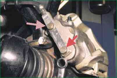
Unscrew the two manifold mounting bolts.
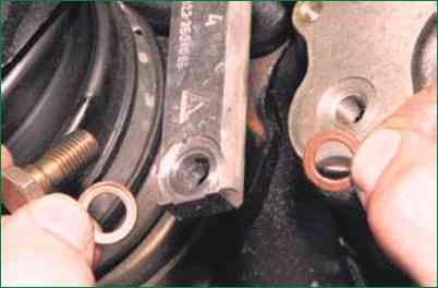
Please note that sealing rings are installed under the bolts.
Replace the heavily compressed ring.
Remove the lower spring arm (described above when removing the pads) remove the cylinder block with brake caliper
Remove brake pads
Clamp brake caliper in vice with soft metal jaw pads
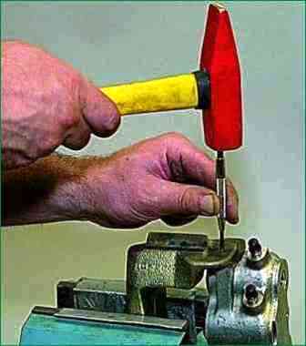
Use a punch to pull off cylinder block retainer
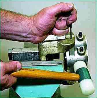
At the same time, we press the cylinder block retainer with a rod with a diameter of 3-4 mm and, striking the cylinder block with a hammer with a plastic tip, begin to move the block along the caliper guides
Having moved the block by 1.5-2.0 mm, we take out the rod.
With a hammer with a plastic tip or a mallet, knock the cylinder block out of the caliper guides
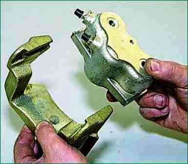
Brake cylinder block and caliper
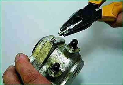
Remove the retainer and its spring from the brake cylinder block socket
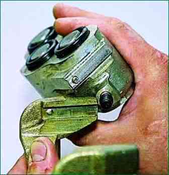
The retainer enters the caliper hole and limits the movement of the cylinder block
We assemble and install the front brake mechanism in the reverse order
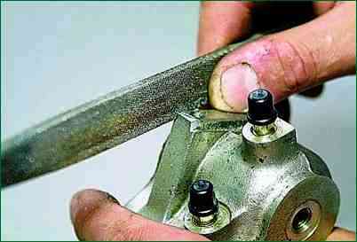
To facilitate assembly, use a file to remove the chamfers from the cylinder block guides
After pressing the retainer into the block socket, insert the block into the caliper grooves.
Using a hammer with a plastic tip, hammer the cylinder block until the retainer enters the caliper hole.
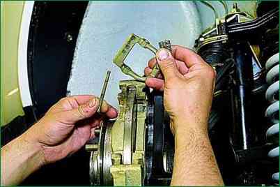
To remove the brake shoe guide, remove the upper pressure lever
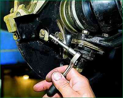
Using a 10 mm head with an extension, unscrew the bolt securing the protective cover to the shoe guide
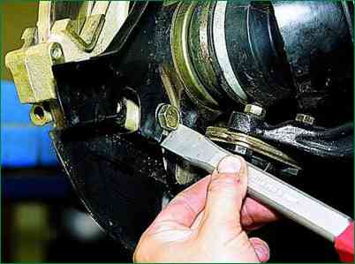
With a chisel, we loosen the two bolts securing the shoe guide to the steering knuckle
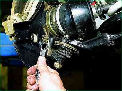
Unscrew the lower bolt with a 17 key
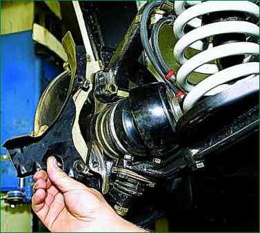
It is more convenient to unscrew the upper bolt with a 17 head
Remove the front casing
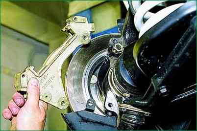
Remove the shoe guide
Assemble the unit in the reverse order and bleed the brake system


