Possible malfunctions of the lighting and light signaling of the Niva Chevrolet
Cause of the malfunction
Remedy
Individual headlights and taillights do not light
- Blown fuses
Check, replace fuses, article - "Fuse and relay boxes"
- Blown lamp filaments
Replace lamps
- Oxidation of contacts of switches or relays
Clean contacts
- Damage to wires, oxidation of their tips or loosening of wire connections
Check, replace damaged wires, clean tips
- Oxidation of contact jumpers at the installation site of the control relay lamps
Check, clean the contact jumpers
The steering column switch levers do not lock
- Destruction of the lever locks
Replace the damaged switch, article - "Removing the steering column switches"
The turn signals do not turn off automatically after completing the turn
- Damage to the mechanism for returning the turn signal switch lever to its original position
Replace the turn signal and headlight switch
The turn signal indicator lamp flashes at double the frequency
- One of the turn signal lamps has burned out
Replace the lamp, article - "How to change bulbs and remove the headlight"
Fogging of the diffuser headlights
- Leakage at the joint where the diffuser is glued to the housing
Plug the drain hole (if any) at the bottom of the housing and lower the headlight with the diffuser into the water. If water gets in, replace the headlight unit
- Water gets in from the engine compartment when washing the car
Remove moisture from the headlight unit
Description of headlight and light signaling circuits
The Niva Chevrolet car uses a headlight unit that combines low-beam and high-beam headlights and turn signals
Headlight connection diagram in Figure 1

The low and high beam headlights are switched on using relays K4 and K5, which are located in the mounting block
The control voltage to the relay is supplied from switch 3 of the headlights, if the switch key 5 of the external lighting is fully pressed
When the low beam is switched on, the low beam lamps light up, and when the high beam is switched on, all the low and high beam lamps light up
You can also briefly switch on the high beam headlights using switch 3, pulling the switch lever towards you. In this case, voltage is supplied to contact "30" of switch 3 directly from power sources
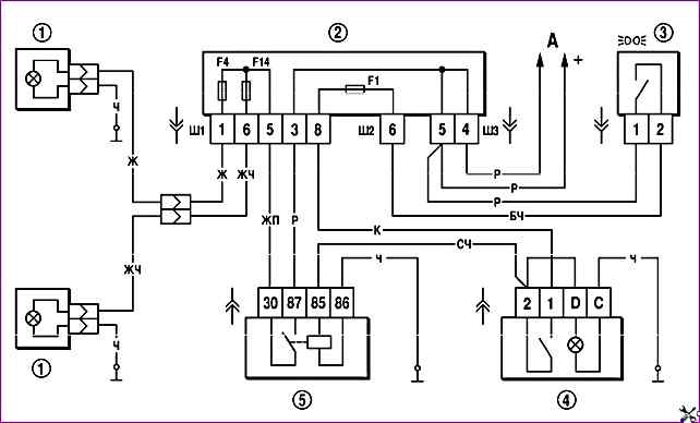
The wiring diagram for the fog lights is shown in Figure 2

The fog lights are switched on by switch 4 using auxiliary relay 5 type 904.3747-11 or 904.3747-11A, installed in the block attached to the rear side of the mounting block
The fog lights can only be switched on if the external lighting is switched on by switch 3
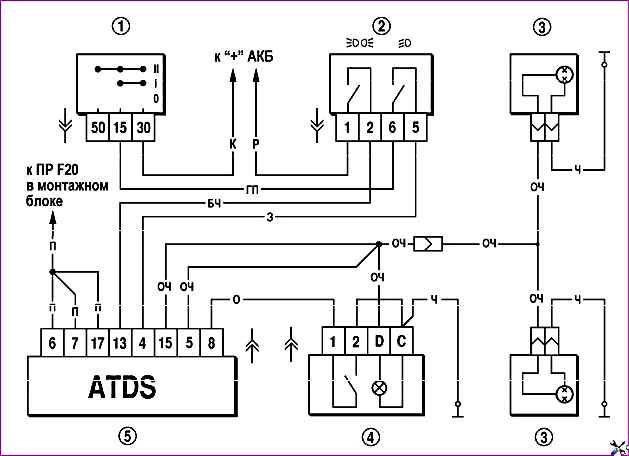
The fog light connection diagram is shown in Figure 3

The fog lamps 3 in the rear lights are switched on by switch 4 via the anti-theft alarm system control unit 5 only if the headlights are on.
When the parking lights are turned off, the rear fog lights are switched off automatically
The external lighting switching diagram is shown in Figure 4

The parking light and brake light lamps are powered via relay K1 for monitoring lamps. If the control relay is not installed in the mounting block, then it is necessary to install the jumpers shown by the arrows in Figure 4
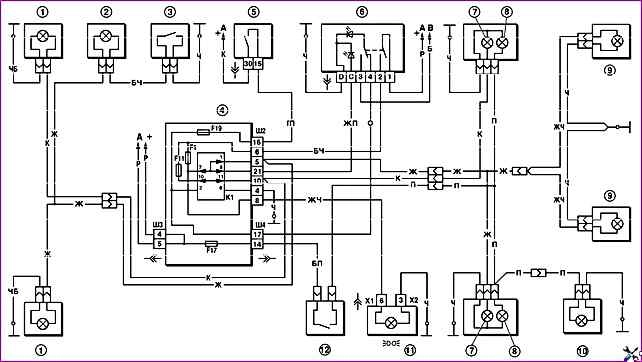
The wiring diagram for the direction indicators and hazard warning lights is shown in Figure 5

The side light is switched on by switch 6 for external lighting
The right or left side turn signals are switched on by switch 3. In hazard warning mode, switch 6 switches on all turn signals
The flashing of the lamps is provided by flasher relay K3 in the mounting block


