Disassembling the gearbox primary shaft
Disassembling the shafts is discussed in the article - "Disassembling and assembling the Lada Priora gearbox"
Clamp the primary shaft in a vice with soft metal jaw pads.
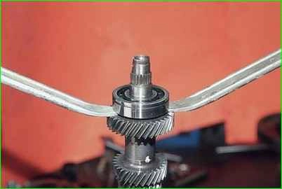
Pry up the rear ball bearing with two mounting blades and press it off.
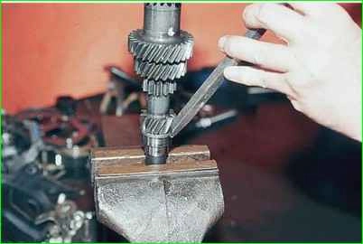
We strike the end of the inner ring of the front roller bearing with a punch.
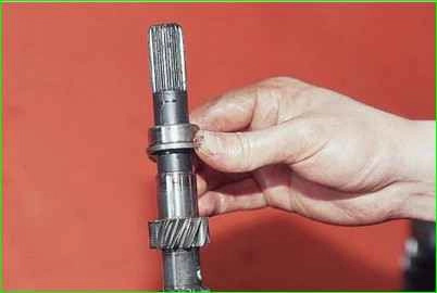
And press ring
Disassembling the secondary shaft
Clamp the secondary shaft in a vice with soft metal jaw pads.
In the gap between the ends of the inner ring of the front shaft bearing and the main gear pinion, insert two mounting blades (to avoid damaging the gear teeth, you can place soft metal spacers under the mounting blades).
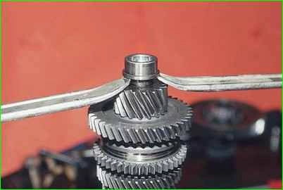
Leaning the mounting blades on the gear.
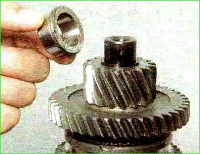
Pressing off the inner ring of the front bearing.
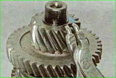
Using pliers for removing retaining rings, unclamp the retaining ring
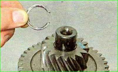
And remove the retaining ring from the front end of the shaft.
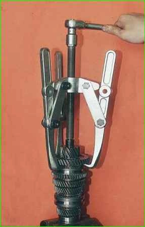
Having hooked the driven gear of the 1st gear with a three-jaw puller
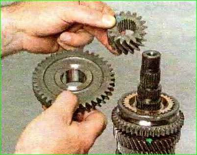
Pressing off the drive gear of the main gear
If there is no puller, place stops under the driven gear of the 1st gear and press off the drive gear of the main gear, striking the end of the shaft with a hammer with a soft metal tip.
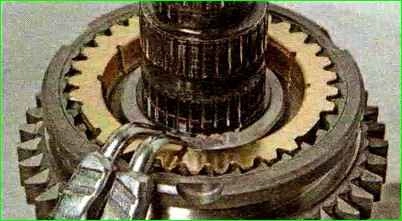
Using pliers for removing retaining rings, we open the retaining ring
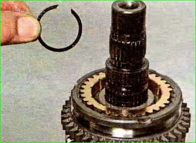
And remove the retaining ring of the hub of the 1st – 2nd gear synchronizer clutch.
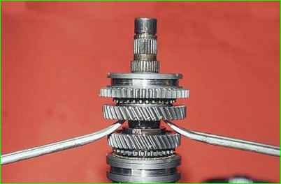
Prying off the driven gear of the 2nd gear with two mounting blades, press the hub of the 1st-2nd gear synchronizer clutch off the shaft.
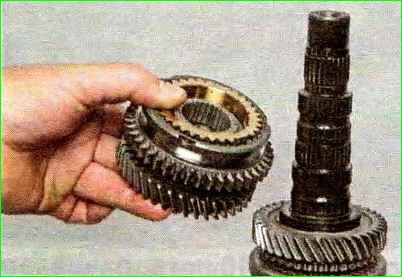
Remove the 1st-2nd gear synchronizer assembly with the driven gear of the 2nd gear.
Disconnect the driven gear of the 1st gear and the 1st-2nd gear synchronizer.
Turn the shaft over vice.
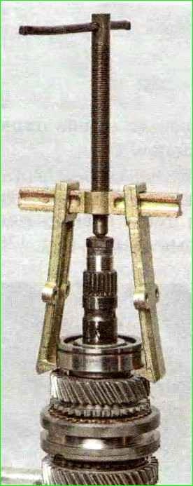
Having installed it on the end shaft stop under the screw of the two-jaw puller, we press the rear bearing of the shaft with the puller.
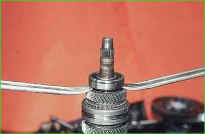
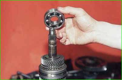
Prying off the rear bearing of the secondary shaft with two mounting blades we press it.
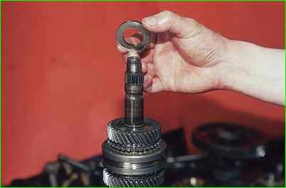
Remove the thrust washer.
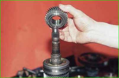
Remove the driven gear of the 4th gear.
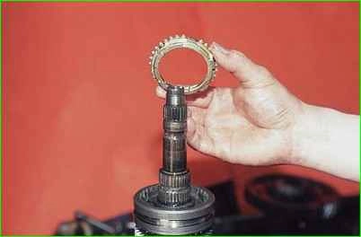
Removing the locking ring of the 4th gear synchronizer
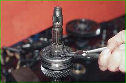
Using round-nose pliers, spread the locking ring of the synchronizer hub and remove it.
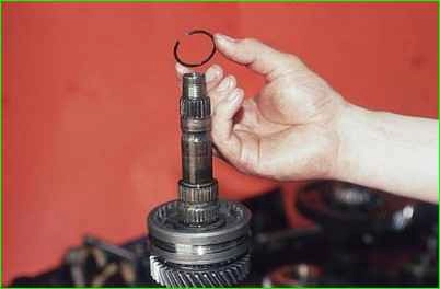
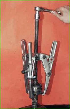
Having grasped the third gear pinion with a three-jaw puller, we press the hub of the sliding clutch of the synchronizer of the third–fourth gears from the shaft
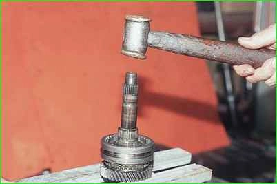
If there is no puller, place stops under the gear and hit the end of the shaft with a copper hammer.
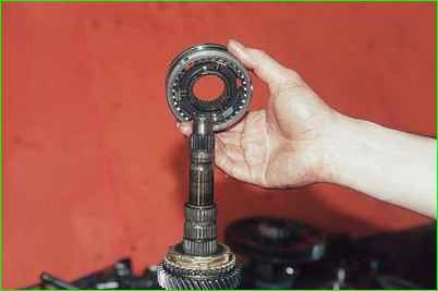
Removing the sliding coupling with the hub synchronizer
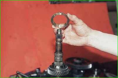
Removing the locking ring of the 3rd gear synchronizer
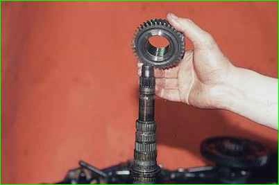
Removing the 3rd gear pinion.
Disassembly and assembly synchronizer
Synchronizers - II, III - IV and V gears are disassembled and assembled in the same way.
We show the disassembly and assembly of the synchronizer using the V gear synchronizer as an example.
Before disassembling, mark the blocking rings and their position relative to the synchronizer clutch.
Remove the blocking rings.
Mark the position of the hub relative to the clutch and the position of the crackers relative to the hub grooves so that they are installed in their original places during subsequent assembly.
To disassemble the synchronizer, carefully slide the clutch along the hub, holding the balls with your hand from "firing".
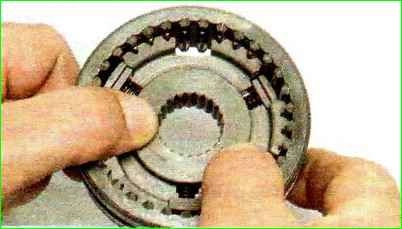
Before assembly, inspect the synchronizer parts.
Narratives and chips on the splines of the hub and coupling, the toothed rims of the locking rings and coupling are unacceptable.
Replace defective parts with new ones.
If the working conical surface of the locking ring is significantly worn (the minimum permissible axial clearance between the ends of the toothed rims of the gear and the locking ring is 0.6 mm), it must be replaced.
For ease of assembly of the synchronizer, generously lubricate the springs, crackers and balls with plastic grease.
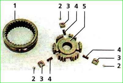
Put the hub on the workbench, insert the springs into the hub sockets, and the crackers into the grooves - in accordance with the previously applied marks.
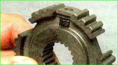
Insert the assembled hub into the coupling, orienting it so that when the ball is subsequently installed, it would be exactly in the middle part of the coupling groove - in its deepest place.
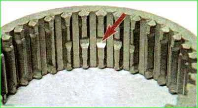
We install the balls in the cracker holes.
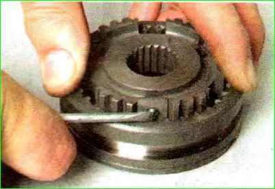
Pressing each ball in turn with a screwdriver, we slide the hub along the splines of the coupling.
When installing the synchronizer on the shaft, the grooves on the coupling and hub should be addressed:
- - for synchronizer I-II gear — to gear I;
- - for synchronizer III-IV gear to gear III;
- - for synchronizer V gear — to thrust plate of shaft bearings.
Grooves on the coupling and hub of the synchronizer
Disassembling the differential
Clamp the driven gear of the main gear in a vice with soft metal jaw pads.
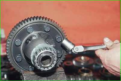
Using a 17 mm socket, unscrew the eight bolts securing the gear to the differential case.
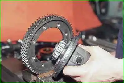
Using a copper hammer, knock out the differential case.
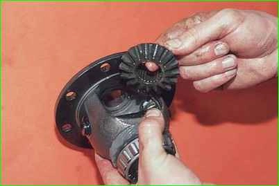
Turning, we take out the drive gears (half-axle) from the box.
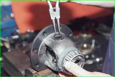
Having clamped the differential box in a vice, we remove the retaining ring from the satellite axle with round-nose pliers.
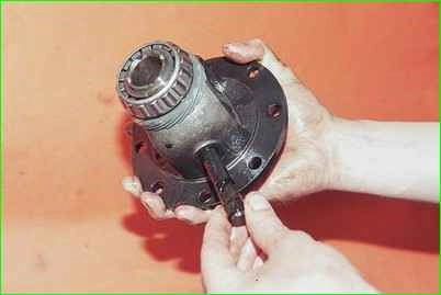
Pressing on the satellite axle, we take it out of the box.
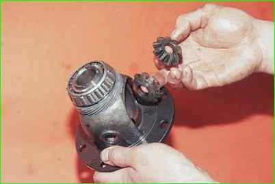
Removing the satellites from the box
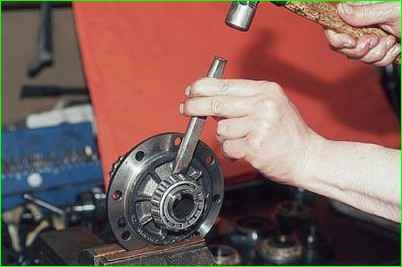
To remove the differential bearings, clamp the box in a vice.
Having inserted a chisel into the gap between the end of the inner bearing ring and the differential box, strike the chisel
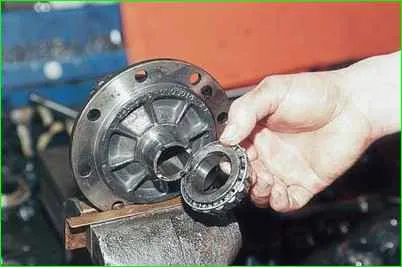
Pressing off the bearing


