We install the car on a lift
For cars with air conditioning - we pump out the refrigerant from the air conditioning system
For cars with a station wagon body, we tilt the rear row of seats forward. Disconnect and lift the floor trim.
Remove the electric fuel pump hatch cover.
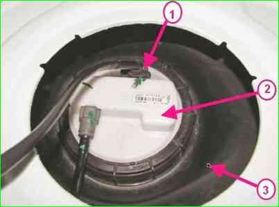
Disconnecting the rear wiring harness connector from the electric fuel pump module: 1 - rear wiring harness connector to the electric fuel pump module; 2 - electric fuel pump module; 3 - fuel tank
Disconnect connector 1 (Fig. 1) of the electric fuel pump module wiring harness.
Start the engine and let it run at idle speed until it stops completely to relieve fuel pressure.
Disconnect the ground terminal from the battery.
Connect the connector of the wiring harness to the fuel pump module.
Install the electric fuel pump hatch cover.
Install and secure the floor trim.
Lower the rear (for 5-seater configuration) or middle (for 7-seater configuration) row of seats.
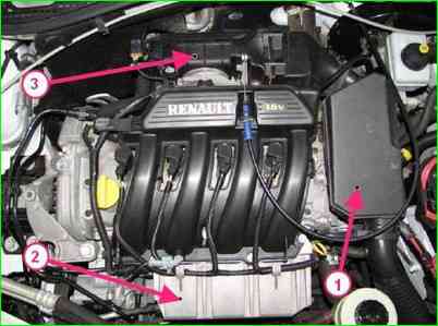
Remove muffler 1 (Fig. 2), intake noise;
- - remove protection 2 fuel rail;
- - remove unit 3 throttle valve
- - remove battery
- - remove battery pan
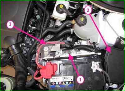
Removing the ECM controller and disconnecting the engine wiring harness: 1 - ECM controller; 2 - mounting block; 3 - engine wiring harness
Remove controller 1 (Fig. 3). Remove the 3-wire harness from the engine from the battery shelf mount.
- - place the harness with fuses and relays on the engine;
- - remove the front wheels;
- - unscrew the hub nuts using the tool (Rou. 604-01 tool, 32-mm replaceable head, ratchet).
- - remove the engine crankcase guard;
- - remove the inner linings and side mudguards;
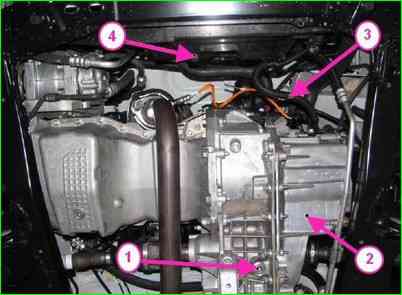
Draining the oil from the gearbox and disconnecting the wiring harness from the electric fan: 1 - gearbox drain plug; 2 - gearbox; 3 - wiring harness to the electric fan of the engine cooling system; 4 - Electric fan of the engine cooling system
Remove the front bumper;
- disconnect the hose of the gasoline vapor recovery system.
Using an 8 mm internal square wrench, unscrew the plug 1 (Fig. 4), the drain hole in the gearbox housing 2 and drain the oil.
- - drain the coolant;
- - disconnect the block (two blocks - for cars with air conditioning) of the harness 3 wires from the electric fan 4 of the engine cooling system.
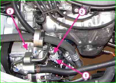
Disconnecting the wiring harness connector of the power steering pressure sensor: 1 - wiring harness connector to the pressure sensor; 2 - pressure sensor: 3 - power steering pump
For vehicles with power steering, additionally disconnect connector 1 (Fig. 5), wiring harness from sensor 2 of pressure in the power steering system.
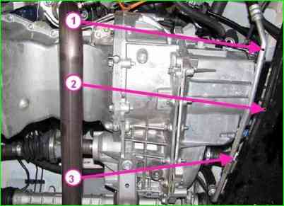
Disconnecting the power steering pipe from the front suspension subframe: 1 - power steering pipe; 2 - front suspension subframe; 3 - power steering pipeline mounting bolt
Using a 10 mm socket, unscrew the bolts and nuts securing the power steering pipelines on the upper part of subframe 2 (Fig. 6), front suspension
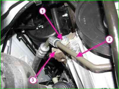
Disconnecting the power steering line from the cylinder block: 1 - power steering line fastening nut: 2 - power steering line; 3 - cylinder block
Using a 13 mm socket, loosen the pipe fasteners on cylinder block 3 (Fig. 7).
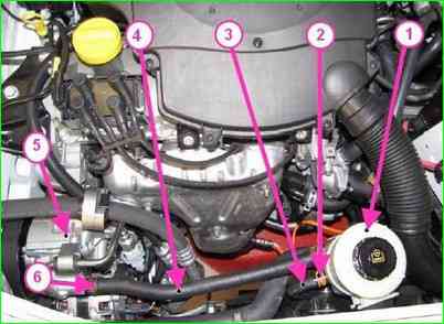
Disconnecting the pipe from the power steering pump: 1 - power steering reservoir; 2 - clamp; 3 - hose; 4 - hose; 5 - power steering pump; 6 - clamp
Unscrew the cap of reservoir 1 (Fig. 8), the power steering pump and pump out the working fluid from the system.
Loosen clamp 6, disconnect hose 4 from pump 5 of the power steering and install plugs in the openings of the pipeline and pump.
Loosen clamp 2, disconnect hose 2 from the reservoir of the power steering pump and install plugs in the openings of the hose and reservoir.
Remove the reservoir of the power steering pump with hose 4 as an assembly. Remove hose 3. from the holder on the housing of the electric fan of the engine cooling system.
Using a 13 mm head, unscrew the bolts securing the high-pressure pipe on the gearbox and the gearbox support.
Loosen clamp 2, disconnect hose 2 from the power steering pump reservoir and install plugs in the holes in the hose and reservoir.
Remove the power steering pump reservoir with hose 4 as an assembly. Remove hose 3. from the holder on the housing of the electric fan of the engine cooling system.
Using a 13 mm head, unscrew the bolts securing the high-pressure pipe to the gearbox and gearbox support.
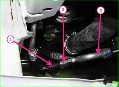
Disconnecting the harness connector from the refrigerant pressure sensor, 1 - harness connector of the refrigerant pressure sensor; 2 - refrigerant pressure sensor; 3 - air conditioning system pipeline
For vehicles with air conditioning, disconnect connector 1 (Fig. 9) of the wire harness from refrigerant pressure sensor 2. Using a 10 mm wrench, loosen the bolt securing the pipeline to the air conditioning compressor, disconnect the pipeline from the compressor and install the plugs.
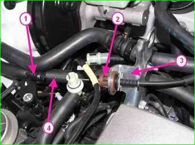
Disconnecting the accelerator drive cable: 1 - accelerator cable ball end; 2 - retainer; 3 - bracket; 4 - accelerator drive cable
Disconnect the ball end 1 (Fig. 10) of the accelerator drive cable from the throttle pipe.
Press the lock 1 and remove the accelerator drive cable 4 from the bracket 3.
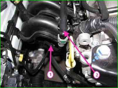
Disconnecting the fuel pipe from the fuel rail: 1 - fuel pipe; 2 - fuel rail
Disconnect the wiring harness connector from the solenoid valve of the adsorber purge.
Disconnect the brake booster vacuum hose from the intake manifold, the crankcase ventilation hose from the intake manifold, the fuel pipe 1 (Fig. 11) from the fuel rail 2.
For vans, first cover the place where the fuel pipe connects to the fuel rail with a rag and prevent fuel from escaping when disconnecting the fuel line, since the pressure in the fuel line is maintained.
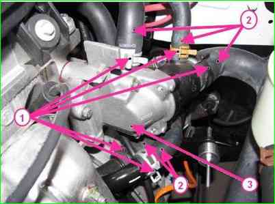
Disconnecting the cooling system hoses: 1 - clamp; 2 - cooling system hose; 3 - thermostat
Unclamp clamps 1 (Fig. 12) and disconnect hoses 2 of the engine cooling system
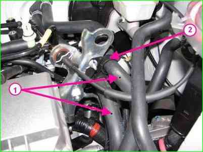
Disconnecting the cooling system hoses: 1 - cooling system hose: 2 - holder
Remove the hoses 1 (Fig. 13), cooling systems from holders 2.
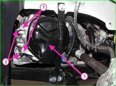
Disconnecting the ground wires from the gearbox: 1 - mounting bolt; 2 - ground wire; 3 - gearbox
Using a 13 mm head with an extension, loosen bolts 1 (Fig. 14), fastenings and disconnect wires 2 "ground" from gearbox 3
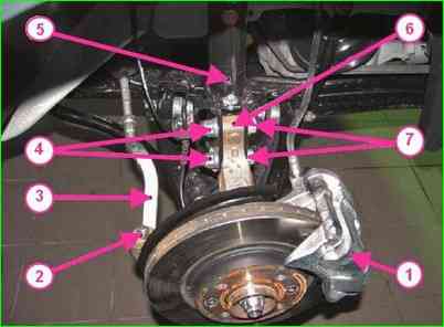
Disconnecting the front suspension components: 1 - front brake; 2 - ball joint pin fastening nut; 3 - outer tie rod end; 4 - shock absorber strut fastening bolt nut; 5 - shock absorber strut; 6 - steering knuckle; 7 - shock absorber strut mounting bolt
Remove the front brakes 1 (Fig. 15)
Using a 16 mm head, unscrew the nuts 2 (Fig. 15) securing the ball joint pins of the outer ends 3 of the steering rods and press the pins out of the steering knuckle arms 6.
Using an 18 mm wrench and an 18 mm head, unscrew the nuts 4 securing the shock absorber struts 5 to the steering knuckles.
Remove the bolts 7 and disconnect the shock absorber struts from the steering knuckles.
Remove the front wheel drives.
Using a 16 mm head, unscrew the nuts 2 (Fig. 15) securing the ball joint pins outer ends 3 steering rods and press out the pins from the levers of the steering knuckles 6.
Using a 18 key, a 18 head, unscrew the nuts 4 of the bolts securing the shock absorber struts 5 to the steering knuckles.
Remove the bolts 7 and disconnect the shock absorber struts from the steering knuckles.
Remove the front wheel drives.
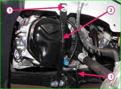
Disconnecting the front suspension elements: 1 - upper mount bolt front suspension subframe stretchers; 2 - front suspension subframe stretcher; 3 - front suspension subframe
Using a 13 mm head, unscrew and remove bolts 1 (Fig. 16), the upper fastening of the struts 2 of the front suspension subframe to the body.
Using a 13 mm head, unscrew the bolts securing the heat shield of the steering gear and remove the heat shield
Using an 18 mm head, unscrew the two bolts securing the steering gear to the front suspension subframe.
Secure the steering gear to the body.
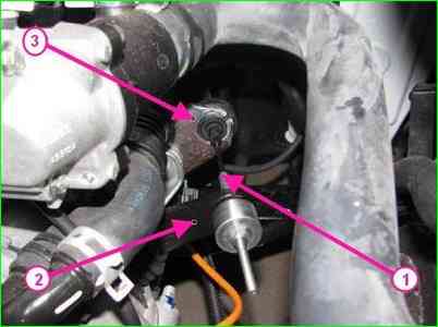
Disconnecting the clutch cable from the gearbox: 1 - clutch cable; 2 - clutch release fork; 3 - clutch cable housing stopper
If the JH3 gearbox is installed, disconnect the clutch cable 1 (Fig. 17) from the clutch release fork 2.
Disconnect the clutch cable from the clutch cable housing stopper.
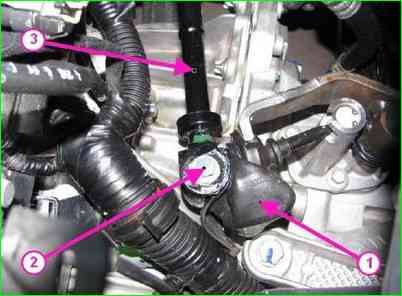
Disconnecting the gearbox control rod: 1 - gear shift lever protective cover; 2 - gearbox control rod mounting bolt; 3 - gearbox control rod
Remove protective cover 1 (Fig. 18) of gear shift lever on gearbox.
Using 10 mm socket head, unscrew bolt 2 securing gearbox control rod.
Secure gearbox control rod 3 to body using hook.

Disconnecting gear selection and shift cables from gearbox: 1 - cable hinge; 2 - gearbox lever; 3 - cable sheath stopper
If the JR5 gearbox is installed, use a flat-head screwdriver to disconnect the hinges 1 (Fig. 19) of the gear selection and shift cables from the gearbox levers 2.
Disconnect the stoppers 3 of the gear selection and shift cable sheaths by pressing the clamps on both sides.
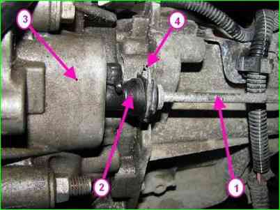
Disconnecting the clutch hydraulic line from the slave cylinder: 1 - line d clutch hydraulic drive; 2 - clutch hydraulic drive slave cylinder; 3 - gearbox; 4 - retainer
Disconnect pipeline 1 (Fig. 20), clutch hydraulic drive from slave cylinder 2, by pressing retainer 4. (Do not pull the retainer, in case of any erroneous action it is necessary to replace the pipeline).
Drain the brake fluid from the pipeline and plug the holes of the pipeline and slave cylinder.
Remove the rear engine mount support.
Disconnect the exhaust system
Move the exhaust pipe towards the rear of the car and hang it on the body using hooks.
Remove the front suspension subframe
Install a crossmember on the gutters of the engine compartment and hook it with two hooks to the lifting eyes on the engine on the timing belt side and on the flywheel side.
Remove the rear suspension support engine.
Move the exhaust pipe towards the rear of the car and hang it on the body using hooks.
Remove the front suspension subframe
Install a crossmember on the gutters of the engine compartment and hook it with two hooks to the lifting eyes on the engine on the timing belt side and on the flywheel side.
Remove the right engine mount support
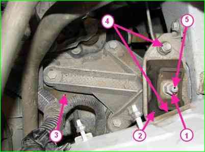
Disconnecting the gearbox from the left suspension mount engine: 1 - gearbox mounting stud nut; 2 - left engine mount support cushion; 3 - gearbox; 4 - left engine mount mounting nut; 5 - gearbox mounting stud
Using a 16 mm head, loosen nut 1 (Figure 21) of the gearbox mounting stud to cushion 2 of the left engine mount.
Lower the engine and gearbox assembly to separate it from the left engine mount.
Using a soft metal punch, knock out key 5 of the gearbox mounting from the left engine mount cushion and separate the engine and gearbox assembly from the mount cushion.
Using an 18 mm head, loosen two nuts 4 and remove the left engine mount cushion.
Install a transport trolley under the engine and gearbox.
Lower the vehicle to the level of the trolley, install shock-absorbing pads and lower the engine and gearbox onto cart.
The engine is installed in the reverse order. This will be discussed in more detail in the next article.


