Removing the engine was discussed in the article - "How to remove the K4M engine from a Lada Largus car"
We bring the trolley with the engine and gearbox assembly under the car, which is raised on a lift.
We lower the car to the engine level and install the engine mount stops.
We install according to the marks on the body made during removal:
- - right engine mount support;
- - left engine mount support.
We look at the article on removing the engine mounts - "How to replace the powertrain mounts"
We install:
- - front suspension subframe;
- - with an 18 head, tighten the two bolts securing the steering gear to the front subframe suspension.
- - using a 13 mm head, screw on the heat shield of the steering gear
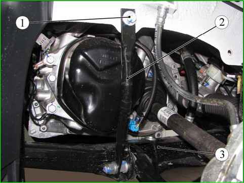
Disconnecting the front suspension elements: 1 - upper mounting bolt of the front suspension subframe brace; 2 - front suspension subframe brace; 3 - front suspension subframe
Using a 13 mm head, tighten bolts 1 (Fig. 1), upper fastening of the front suspension subframe struts
Install the front wheel drives.
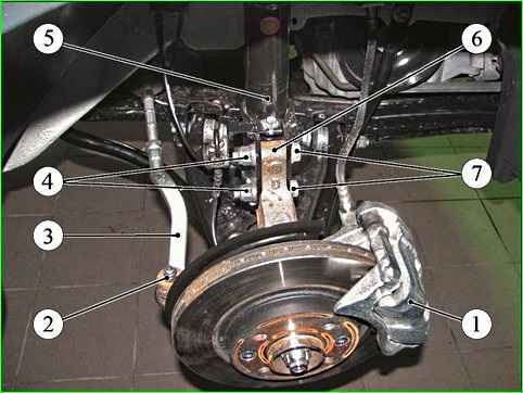
Disconnecting the front suspension components: 1 - front brake; 2 - ball joint pin fastening nut; 3 - outer tie rod end; 4 - shock absorber strut fastening bolt nut; 5 - shock absorber strut; 6 - steering knuckle; 7 - shock absorber strut mounting bolt
Using a 18 mm head, tighten bolts 7, securing shock absorber struts 5 to steering knuckles 6 (Fig. 2).
- - with a 16 mm head, ball joints of outer ends 3 of steering rods;
- - with a 18 mm head, front brakes;
Tightening torques:
- - steering gear mounting bolts to front suspension subframe 105 Nm (10.5 kgf.m) (18 mm replaceable head);
- - upper bolts securing front suspension subframe struts 21 Nm (2.1 kgf.m) (13 mm replaceable head);
- - mounting bolts shock absorber strut to steering knuckle 105 Nm (10.5 kgf.m) (replaceable head 18);
- - nuts for fastening ball joint pins of steering rod ends 37 Nm (3.7 kgf.m) (replaceable head 16);
- - front brake fastening bolts 105 Nm (10.5 kgf.m) (replaceable head 18).
We install the "ground" wires on the gearbox (replaceable head 13, extension, ratchet).
Tightening torque of bolts 1, figure 2-17, fastening wires 2 "ground" on the gearbox 21 Nm (2.1 kgf.m) (replaceable head 13, extension, torque wrench).
We install the exhaust system gases.
Installing the rear engine mount support.
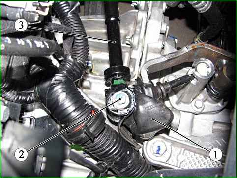
Disconnecting the gearbox control rod: 1 - gear shift lever protective cover; 2 - gearbox control rod mounting bolt; 3 - gearbox control rod
For cars with JH3 gearbox
Apply Molykote-33 grease to bolt 2 (Fig. 3) securing the gearbox control rod.
Attach gearbox control rod 3 to the gearbox.
Tightening torque of the gearbox control rod securing bolt to the gearbox 27.5 Nm (2.75 kgf.m) (10 replaceable head, extension, torque wrench).
Install protective cover 1 on the gearshift lever.
Install the clutch cable

Disconnecting the gear selection and shift cables from the gearbox: 1 - cable hinge; 2 - gearbox lever; 3 - cable sheath stopper
For cars with JR5 gearbox
Install stoppers 3 (Fig. 4), gear selection and shift cable sheaths on the gearbox bracket.
Attach hinges 1 of the gear selection and shift cables to the levers on the gearbox.
Remove plugs from the holes in the pipeline and the working cylinder of the clutch hydraulic drive.
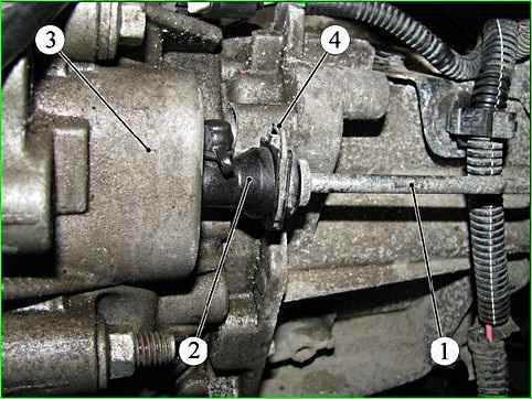
Disconnecting the clutch hydraulic drive line from the working cylinder: 1 - clutch hydraulic drive line; 2 - clutch hydraulic drive working cylinder; 3 - gearbox; 4 - retainer
Connect pipeline 1 (Fig. 5), clutch hydraulic drive to slave cylinder 2, by pressing retainer 4.
Bleed air from clutch hydraulic drive circuit.
For vehicles with power steering:
Install the power steering reservoir.
Install and connect high and low pressure power steering pipelines.
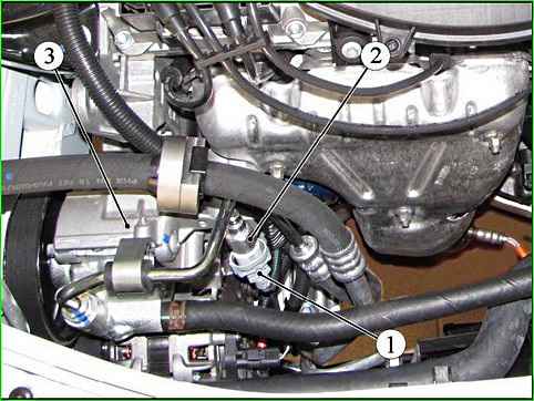
Disconnecting Wiring harness connectors from the power steering pressure sensor: 1 - wiring harness connector to the pressure sensor; 2 - pressure sensor; 3 - power steering pump
Connect connector 2 (Fig. 6) of the wiring harness to the pressure sensor in the power steering system.
Install the cooling system hoses in the holder.
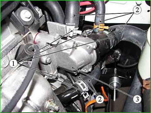
Disconnecting the cooling system hoses: 1 - clamp; 2 - cooling system hose; 3 - thermostat
Connect hoses 2 (Fig. 7), engine cooling system with new clamps:
- - to thermostat housing 3;
- - to coolant supply pipe;
- - to engine cooling system radiator.
Connect:
- - brake booster vacuum hose to intake manifold;
- - crankcase ventilation hose to intake manifold;
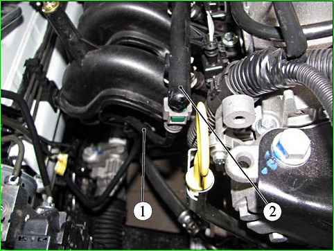
Disconnecting the fuel pipe from the fuel rail: 1 - fuel pipe; 2 - fuel rail
Connect:
- - fuel supply line 1 (Fig. 8), to fuel rail 2;
- - wiring harness block to the electromagnetic valve of the adsorber purge;
Connect:
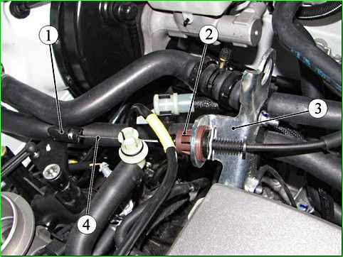
Disconnecting the accelerator drive cable: 1 - ball end of the accelerator drive cable; 2 - retainer; 3 - bracket; 4 - accelerator drive cable
- - clamp 2 (Fig. 9), throttle drive cable sheath;
- - ball end 1 of the drive cable to the throttle valve unit;
Attach:
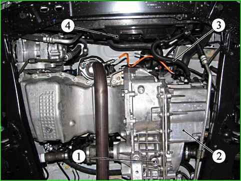
Draining oil from the gearbox and disconnecting the wiring harness from the electric fan: 1 - gearbox drain plug; 2 - gearbox; 3 - wiring harness to the electric fan of the engine cooling system; 4 - electric fan of the engine cooling system
- - connectors of wiring harness 3 (Fig. 10), to electric fan 4 of the engine cooling system;
- - wiring harness to the fan of the cooling system.
Replace the sealing gasket of plug 1 of the drain hole and install the plug with a new gasket.
Tightening torque of the drain hole plug 22 Nm (2.2 kgf.m) (wrench for an internal square of 8 mm, replaceable nozzle for an internal square of 8 mm, torque wrench).
Unscrew the plug of the filler hole.
Fill the oil into the gearbox. The oil level should reach the lower edge of the filler hole (transmission oil, filling rate: for JH3 - 2.8 l; for JR5 - 2.5 l).
Install the filler plug.
Fill the cooling system with fluid.
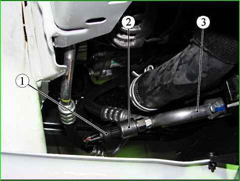
Disconnecting the harness connector from the refrigerant pressure sensor: 1 - refrigerant pressure sensor wiring harness connector; 2 - refrigerant pressure sensor; 3 - air conditioning system pipeline
For vehicles with air conditioning system, additionally connect block 1, wiring harness to refrigerant pressure sensor 2
Remove the process plugs and connect the pipeline to the air conditioning compressor
Attach the fuel vapor recovery system hose;
Install the front bumper.
Install the hub mounting nuts using the tool. Tightening torque of the hub mounting nut 280 Nm (28.0 kgf.m) (device Rou. 604-01, replaceable head 32, ratchet, torque wrench).
We install:
- - side mudguards and linings;
- - engine crankcase protection;
- - front wheels;
- - injection system ECU.
We install:
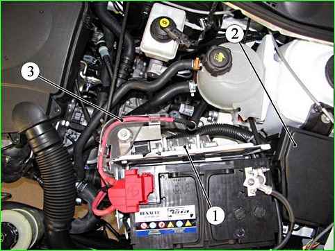
Removing the ECM and disconnecting the engine wiring harness: 1 - ECM; 2 - mounting block; 3 - engine wiring harness
- - fuse holders and relay blocks in block 1 (Fig. 12), relays and fuses;
- - fuse and relay box cover.
Install the 3 engine wiring harness into the mount on the shelf under the battery.
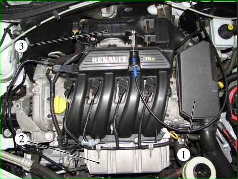
Removing the intake system components of a car with a K4M engine: 1 intake noise muffler; 2 - fuel rail protection; 3 - throttle valve unit
Install unit 3 (Fig. 13), throttle valve.
Install protection 2 fuel rail.
Install muffler 1 intake noise, pipe 1 air intake, battery pan, battery
Additionally for vehicles with power steering:
Fill the power steering system with working fluid (power steering oil Mobil ATF 52475).
Bleed air from the power steering system by turning the steering wheel from the extreme left position to the extreme right.
Start the engine and bleed air from the power steering system by turning the steering wheel from the extreme left position to the extreme right.
We bring the level of the working fluid in the power steering pump reservoir to normal.
We make sure that there is no leakage of the working fluid.
We remove air from the engine cooling system
For cars with air conditioning - we fill the refrigerant into the air conditioning system circuit.


