Adjusting the installation angles and toe-in of the front wheels of the GAZ-3110
It is recommended to adjust wheel alignment angles on a stand at service stations. The adjustment should be made in the following sequence:
- - wheel camber adjustment;
- - adjustment of the longitudinal inclination of the king pin;
- - wheel toe adjustment.
Front wheel alignment angles:
- – camber 0°±30'
- – the difference in camber values for the right and left wheels is no more than 30'
- – tilt the lower end of the kingpin forward from 4°30' to 6° (from 5° to 6°30')**
- – the difference in the king pin angle values for the right and left wheels is no more than 30'
**The value of the longitudinal inclination angle of the king pin for the total vehicle weight (for reference). Load - 5 people or a load of 150 kg in the front and 225 kg in the rear seats.
Wheel toe-in:
- – when measuring on tires 1-2 mm (7'-14')
- – when measured on rims 0.7-1.3 mm
- – maximum rotation angle of the inner front wheel (not adjustable) 40°-42°
Adjustment is carried out with the pendulum arm, steering mechanism, steering linkage, upper and lower front suspension arms securely fastened, front wheel hub bearings adjusted, front suspension and steering linkage in working order, tire pressure normal.
When checking the angles, the car's wheels should be in the straight-ahead position.
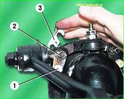
Adjustment of camber and longitudinal inclination of the king pin is carried out by changing the number of adjusting shims 3.
Changing an equal number of shims in the front and rear mounting of the upper arm axle changes the wheel camber.
One 1.0 mm thick spacer changes wheel camber by approximately 0°12'
Adjustment of the longitudinal inclination of the kingpin is carried out by changing the number of shims 3 only in the front or rear fastening of the upper arm axis.
One shim changes the kingpin angle by approximately 0°25'
To adjust the angles, loosen nut 2 and bolt 1, select the required number of spacers 3, tighten bolts 1 and then nuts 2 to a torque of 44–56 Nm (4.4–5.6 kg/cm).
Adjusting the toe-in of the front wheels is carried out by turning the adjusting tubes of the side steering rods.
Adjustment on the outer side surfaces of the tires is carried out on a stand.
Before adjustment, you need to find the points of equal lateral runout of the tires and turn the wheels so that they are located in a horizontal plane.
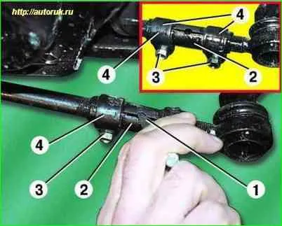
If, during straight-line movement, the steering wheel was in the correct position (the steering wheel spokes were positioned horizontally), and the toe-in value differed from the nominal value by no more than 3-4 mm, then the toe-in adjustment can be done by changing the length of any lateral rod.
To do this, loosen the tightening of bolts 3 of clamps 4.
Then turn adjusting tube 2 using bit 1 until the convergence value corresponds to the nominal value.
Turn the clamps 4 so that the ears of the clamps are directed in the same direction and lie in the same plane.
Tighten bolts 3 to a torque of 15–18 Nm (1.5–1.8 kg/cm).
If the steering rods were disassembled before adjustment and their length was changed, adjust the toe-in in the following order:
- - set the steering wheel to the straight-line position (the wheel spokes are horizontal);
- - set the left wheel to the straight-line position by turning the left adjustment tube;
- - turn the right adjusting tube to adjust the convergence;
- - turn the clamps of the adjusting tubes so that the ears of the clamps are directed in one direction and lie in the same plane, and tighten the bolts to a torque of 15-18 Nm (1.5-1.8 kg/cm).
The “old-fashioned” method of checking and setting angles
Gross violations in the installation corners can be determined using available tools (calipers and plumb line)
The adjustment sequence is as follows:
- - adjust the camber of the front wheels;
- - angle of longitudinal inclination of the king pin;
- - wheel alignment.
It is difficult to measure the angle of inclination of the kingpin with the required accuracy without special equipment, so we recommend not changing the factory settings (preserve the difference in the thickness of the gaskets for the front and rear mounting of the upper arm axle).
Before adjusting, check m:
- play in the front suspension, wheel bearings and steering; tire pressure. We find the points of equal lateral runout of the tires and rims of the front wheels, marking them with chalk.
We place the car on a horizontal platform with the wheels straight.
Camber adjustment
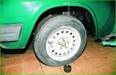
We install the front wheels so that the points of their equal lateral runout are located vertically.
We hang a plumb line on the front fender of the car, in the center of the wheel.
We lower the weight of the plumb line into a container with oil, but it should not touch the bottom.
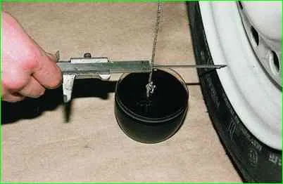
Measure the distance from the wheel rim to the plumb line at the lowest point
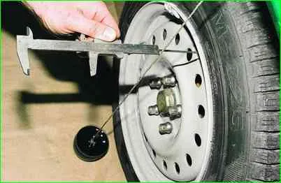
Measure the distance from the wheel rim to the cord at the top point
Repeat measurements for the second wheel. camber (the difference between the distances to the upper and lower points) should be 0±3.5 mm.
If necessary, loosen the nuts and bolts securing the axle of the upper arms and select adjusting shims to obtain the required camber value.
In order not to disturb the longitudinal inclination of the kingpin, we add or remove the same number of spacers from the front and rear axle mounts.
Adding 1mm shims increases camber by approximately 1.2 mm.
Toe adjustment
We install the wheels so that 2 points of equal runout on the sidewall of the tire on one side are horizontal, and the steering wheel is in the middle position (according to the number of revolutions from the extreme positions).
We make a spacer 28 mm high from a wooden block.
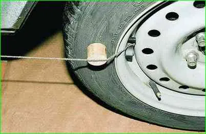
Attach a magnet to the end of the cord (3 m) and attach it to the rim of the rear wheel.
Place the gasket and pull the cord along the car.
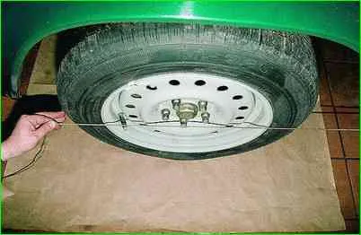
The cord should touch both sides of the front tire sidewall.
If necessary, loosen the two clamp bolts and rotate the steering rod adjusting tube to set the wheel to the required position.


