In the fuel injection engine power system, the pressure is 30 MPa (3 kgf/cm²)
Therefore, it is forbidden to loosen the connections of the fuel lines while the engine is running or immediately after stopping it
To carry out repair work on the power system on a freshly stopped engine, it is necessary to first reduce the pressure in the power system
2-3 hours after stopping the engine, the pressure in the system drops to almost zero.
A fundamental feature of the ZMZ-4062 engine power system is the absence of a carburetor, which combines the functions of mixture formation and dosing of the air-fuel mixture into the engine cylinders.
In the distributed injection system installed on this engine, these functions are separated - the injectors carry out dosed injection of fuel into the intake pipe, and the air required at each moment of engine operation is supplied by a system consisting of a throttle and an idle air regulator.
The fuel injection system and ignition system are controlled by an electronic engine control unit, which continuously monitors, using appropriate sensors, the amount of engine load, vehicle speed, thermal state of the engine and the environment, and the optimal combustion process in the engine cylinders.
This control method makes it possible to ensure the optimal composition of the combustible mixture at each specific moment of engine operation, which allows you to obtain maximum power with the lowest possible fuel consumption and low exhaust gas toxicity.
The diagram of the fuel injection system is shown in the figure.
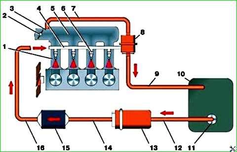
Fuel tank 10 is welded, stamped, secured with two steel clamps through gaskets under the floor of the luggage compartment.
A fuel intake and a fuel level sensor are installed at the top of the fuel tank.
Next to the fuel tank, under the floor of the body, there is an electric fuel pump connected by a fuel line to the fuel tank.
To reduce vibration, the pump bracket is attached to the floor through rubber pads.
From the pump, fuel is supplied to the fuel filter installed in the engine compartment, and from there it enters the engine fuel line mounted on the engine intake pipe.
Fuel is injected from the engine fuel line by injectors into the intake pipe.
Excess fuel is drained into the fuel tank through a pressure relief valve installed at the rear end of the engine fuel line.
In addition to the element power supply system shown in the diagram, it includes an air filter installed in the engine compartment, connected by a rubber hose to a mass air flow sensor, which in turn is connected to a throttle mounted on the air receiver, as well as an idle speed regulator, also installed on the air receiver.
The nozzle is an electromechanical valve in which the shut-off valve needle is pressed to the seat by a spring.

When an electrical impulse is applied from the control unit to the electromagnet winding, the needle rises and opens the nozzle hole, through which fuel is supplied to the engine inlet pipe.
The amount of fuel injected by the injector depends on the duration of the electrical pulse.
The pressure reducing valve is a container separated by a diaphragm on which a valve is attached that closes the fuel drain hole under the action of a spring.

The pressure reducing valve maintains a constant pressure in the power system of about 0.3 MPa.
The upper part of the pressure relief valve is connected to the receiver with a vacuum hose.
When the pressure drop in the receiver is not higher than 0.3 MPa, the valve is closed and the pressure in the supply system rises.
When the fuel pressure reaches more than 0.3 MPa, the membrane bends, opening a hole, and excess fuel drains into fuel tank.
As soon as the fuel pressure drops to 0.3 MPa, the membrane returns to its original position and closes the fuel drain hole.
The mass air flow sensor is used to determine the amount of air entering the engine cylinders.

Signals from the sensor enter the engine control unit and are one of the parameters that determine the duration of fuel injection by the injectors - the amount of fuel depends on the amount of air at any given moment.
The main element of the sensor is a platinum filament, heated up to 150 °C during operation.
As the air intake from the engine passes through the sensor housing, the filament is cooled, and the electronic circuit of the sensor constantly strives to maintain a filament temperature of 150 °C.
The electrical power expended to maintain the filament temperature is the parameter by which the engine control unit determines the duration of the electrical pulse supplied to the injectors.
The degree of cooling of the platinum filament depends not only on the quantity, but also on the temperature of the passing air, determined by a thermal compensation resistor, which accordingly corrects the signal supplied by the sensor to the control unit.
To make it possible to adjust the amount of carbon monoxide in the exhaust gases at idle speed, the electronic module has a variable resistor, with the screw of which you can manually change the magnitude of the signal supplied by the sensor to the electronic control unit, thereby changing the duration of the pulse supplied to the injectors, and therefore, the amount of fuel injected.
To clean the platinum thread from contaminants, the electronic module periodically supplies it with increased voltage, causing heating to 1000 °C. In this case, all deposits burn out.
If the sensor fails, the engine control unit turns on a backup program that ensures engine operation with slightly different, but acceptable power and consumption characteristics.
At the same time, the warning lamp in the instrument cluster lights up.
The idle speed regulator is used to maintain a constant set engine idle speed when starting it, warming it up and changing the load caused by turning on auxiliary equipment.

The regulator is a solenoid-controlled spool valve and is used to supply additional air to the intake pipe, bypassing the throttle valve.
If the idle speed regulator fails or there is no contact in the plug block, the stability of the idle speed is disrupted (the speed “floats”). At the same time, the warning lamp in the instrument cluster lights up.
If the idle speed is unstable and the warning lamp does not light up, you need to check the tightness of the connecting hoses.
The throttle position sensor, which is a dual variable semiconductor resistor, is installed on the throttle on the same axis as the throttle valve.

Using the sensor signal, the engine control unit determines the position of the throttle valve in order to calculate the duration of the electrical pulse supplied to the injectors and the optimal ignition timing.
The determining signal is the magnitude of the voltage drop across the variable resistor of the sensor, which changes depending on the position of the throttle valve (fully closed, partially open, fully open).
If a sensor fails, the engine control unit operates according to the backup program stored in ((memory)), using data from other sensors. At the same time, the warning lamp in the instrument cluster lights up.
The speed and timing sensor is located at the front of the engine on the right side.
Using the sensor signal, the engine control unit determines the angular position of the crankshaft and its rotation speed.

According to the frequency of signals generated by the sensor when rotating the synchronization disk, mounted on the crankshaft pulley, the control unit determines the engine crankshaft speed, synchronizing the fuel supply by the injectors and the ignition timing with the engine operating process.
If the crankshaft position sensor fails, the engine will not start, since the control unit, without receiving a signal from the sensor, will not turn on the injection and ignition systems.
The knock sensor is located at the top of the engine block on the right side and is secured with a nut and spring washer.
It is used to determine the moment when detonation occurs when the engine is running on gasoline with a lower octane number than required when the engine overheats or the driver selects the wrong driving mode.
The operation of the knock sensor is based on the principle of the piezoelectric effect.
When a mechanical impact is applied to a piezoelectric element made of metal-ceramic, an electric current arises in it.
Mechanical action is carried out by an inertial washer, which perceives the shock wave that occurs in the combustion chamber and the engine cylinder during detonation combustion of the fuel mixture.
At the same time, a voltage pulse appears in the sensor, which it transmits to the control unit from the plug.
Based on this signal, the control unit adjusts the ignition timing until detonation stops.
Failure of the sensor or a malfunction in its electrical circuit will result in the absence of an optimal change in the ignition timing in the presence of detonation.
At the same time, the indicator lamp in the instrument cluster will light up.
The phase sensor is located at the rear of the cylinder head on the left side. The operating principle of the sensor is based on the Hall effect.
When a metal plate mounted on the camshaft passes past the end of the sensor core, an impulse is generated that allows the control unit to determine the moment the piston of the 1st cylinder is at top dead center during the compression stroke and send an injection signal to the injector of this particular cylinder.
Further supply of pulses is carried out by the control unit in accordance with the order of operation of the cylinders inherent in its program.
If the phase sensor fails, the control unit switches to backup mode with fuel supplied to all cylinders simultaneously.
At the same time, engine performance is maintained, but fuel consumption increases significantly.
A sensor malfunction is indicated by a warning lamp in the instrument cluster.
The air filter with a dry replaceable filter element made of corrugated filter paper is located in the right front part of the engine compartment.
The filter element is secured to the filter cover with a wing nut, and the cover is secured to the body with three spring clips.
The rotary-type electric fuel pump driven by a DC electric motor is located directly in the pump housing and operates in the fuel.
In this regard, there are no seals of any moving parts in the pump, and the rubbing surfaces are lubricated by flowing fuel.
The check valve installed in the pump prevents fuel from flowing from the high pressure fuel line into the tank after the ignition is turned off.
The electric fuel pump is of a non-separable design and must be replaced if it fails.
The fuel filter is installed in the engine compartment above the vacuum brake booster.
Replacing the standard filter with another one, for example a standardized one in a plastic casing, is strictly prohibited due to high fuel pressure in the system.
The closed-type engine crankcase ventilation system is forced, operating due to the vacuum in the intake manifold.
When the engine is idling and at low loads, when the throttle valve is closed, crankcase gases are sucked through the hose of the small branch of the system directly into the engine intake manifold and then into the cylinders.
In other modes, crankcase gases are suctioned through the hose of the main branch of the system into the throttle and from there into the intake manifold.
During operation, it is necessary to ensure the tightness of the connection and the cleanliness of the pipelines, since if the crankcase ventilation system is not working, rapid oxidation and aging of the engine oil occurs.
Clogging of the system pipelines leads to oil leakage through the oil seals and engine seals due to an excessive increase in crankcase gas pressure.
")

")
")
")
")
")
")
")