The car uses an independent kingpin front suspension
Beam 2 of the front suspension (cross member) is bolted to the side members of the body and is a supporting part for fastening the vehicle's power unit and suspension elements.
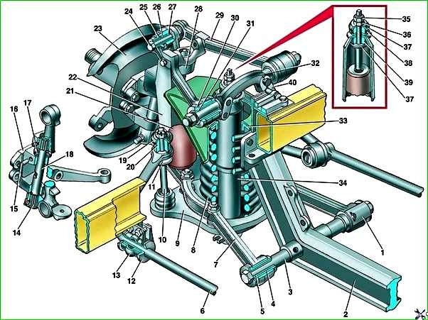
The upper 29 and lower 7 wishbones ensure independent movement of each of the front wheels in the vertical plane (when overcoming road obstacles).
Rubber-metal bushings are pressed into the eyes of the inner ends of the upper and lower arms, through which the arms are connected to the axles and secured to the axles with nuts.
The axes of the upper arms 29 are secured to the beam with bolts, and the axes of the lower arms 7 are threaded pins 3 screwed into the threaded bushings of the front suspension beam.
The axes of the lower arms are secured against spontaneous unscrewing with locking brackets 1, which are bolted to the beam bushings.
The 28 upper arms with supports are bolted to the upper arms with buffer bolts. The 9 spring cups of the front suspension are screwed to the lower arms.
The struts 22 of the front suspension with threaded hinges pressed into the heads of the struts are secured to the eyes of the outer ends of the levers using pins 24.
The design of the upper and lower threaded hinges of the rack is the same.
The outer bushing 26 has an internal thread and is pressed into the head of the rack. A spacer sleeve 27 with an external thread is screwed into it.
In this case, the outer bushing is motionless during operation relative to the strut, and the immobility of the spacer sleeve in relation to the suspension arms is ensured by compressing the bushing post between the levers with a finger.
The threaded joint for protection against dirt is sealed with 25 rubber O-rings.
During operation, threaded joints are periodically lubricated with transmission oil through grease nipples.
Rubber buffers with 21 compression strokes are attached to the racks.
Between the axles of the upper arms and the front suspension beam, adjustment plates 40 are installed, which provide adjustment of the wheel camber and longitudinal angles of the king pins.
The steering knuckles 16 are connected to the struts by pins with needle bearings.
To absorb axial loads, the pivot joints have thrust ball bearings 17 installed between the upper ears of the steering knuckles and struts.
All bearings are protected from contamination by rubber seals.
In operation, the pin bearings are lubricated with transmission oil through grease nipples in accordance with the accepted frequency.
The pins 18 in the steering knuckles are locked with pins 15. The ends of the pins are closed with removable plugs.
The steering linkage steering arms, brake shields 23 and disc brake brackets are bolted to the steering knuckles.
The front wheel hubs are installed on the steering knuckle axles.
The pumping hub rotates on two tapered roller bearings.
A brake disc is installed on the hub.
The hub is sealed with an oil seal on the brake shield side, and with a cap on the outside.
The tightening of the hub bearings is adjusted using a disposable nut.
The nut is fixed on the hub axle by jamming the nut flange so that the crumpled part of the nut fits into the groove of the steering knuckle axle.
Springs 8 of the front suspension are cylindrical.
The upper ends of the springs rest against the heads of the front suspension beam through rubber gaskets 33, and the lower ends rest against the cups 9 of the springs installed on the lower arms.
Shock absorbers 34 front suspension - telescopic, hydraulic, double-acting.
Shock absorbers are installed inside the springs.
The upper parts of the rods protruding from the shock absorbers are protected from dirt by rubber caps.
The upper ends of the shock absorbers through rubber cushionski 38 and 39 are fixed in the heads of the front suspension beam, and the lower ones are attached to the spring cups.
The anti-roll bar 6 is attached to the side members through two cushions 12 with clips 13 and to the front suspension spring cups through struts 10.
The stabilizer struts 10 are attached to the ends of the stabilizer bar and to the spring cups through rubber pads 20 and 11.