Diaphragm spring clutch
Car clutch is single-plate dry with a central diaphragm spring, hydraulically driven
The clutch release bearing is in constant contact with the diaphragm spring petals.
The free play of the clutch release fork is not adjustable.
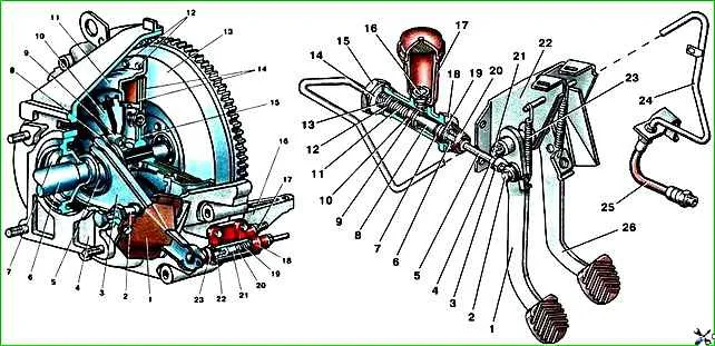
Clutch drive: 1 - clutch pedal; 2 - pusher axis; 3 - pusher eye; 4 - nut; 5 - pusher; 6 - retaining ring; 7 - cuff; 8 - piston; 9 - valve; 10 - inner cuff; 11 - spring; 12 - valve cage; 13 - thrust ring; 14 - gasket; 15, 16 - fittings; 17 - tank; 18 - main cylinder; 19 - thrust washer; 20 - protective cap; 21 - clutch pedal axis; 22 - bracket; 23 - return spring; 24 - tube; 25 - hose; 26 - brake pedal
Clutch housing 4 (see Fig. 1.
Clutch with diaphragm spring) is one-piece, cast from aluminum alloy, attached to the cylinder block with ten bolts of different lengths.
Of these, the two right bolts are also fastenings for the starter and the eye.
In the lower front part of the crankcase there is a crankcase amplifier 16, which is attached directly to the crankcase with two lower bolts, and to the cylinder block with four bolts.
The pressure plate 11 is connected to the casing by connecting plates.
The connecting plates are riveted to the casing on one side and to the pressure plate on the other.
A diaphragm spring 10 of the disc type with slots is installed between the pressure plate and the casing and is clamped by two support rings.
The driven disk 15 consists of a hub with a torsional vibration damper and a disk with friction linings 14.
The friction linings are riveted to the disc leaf springs with aluminum rivets on both sides.
The clutch release drive is hydraulic and consists of 18 main and 18 working cylinders, 1 clutch pedal, 24 hydraulic clutch release tube and 25 hose.
The clutch pedal is connected to the master cylinder using a pusher 5, which has an adjustment unit.
Clutch release fork 3 (see Fig. 1 Clutch with diaphragm spring) stamped.
It transmits force from pusher 22 of the working cylinder to clutch release bearing 9.
The axis of rotation of the fork is ball pin 2, which is attached to the rear of the clutch housing with a bolt.
To protect clutch parts from dust and dirt, a dirt-proof cover 1 is used, secured to the clutch housing with one bolt.
Clutch release bearing 9 is a closed type and does not require lubrication during operation. It is pressed onto clutch release clutch 8.
Nominal and maximum permissible dimensions, fit of mating clutch parts with a diaphragm spring
Friction lining diameter:
- – outer 225 mm;
- - internal 150 mm
Thickness of the friction lining - 3.5 mm
The minimum size of the rivet head recessed relative to the friction lining is 0.2 mm
Clutch pedal travel: 145-160 mm
Table of mating parts:
Name of part - Nominal diameter, mm - Name of mating parts - Nominal diameter, mm:
- Clutch release bearing - 50-0.012 - clutch release bearing coupling - 50+0.027, 50+0.009;
- Guide sleeve - 38-0.050, 38-0.065 - clutch release bearing clutch - 38+0.027;
- Gearbox input shaft - 4-0.017, 4-0.017 spline width - Driven disk - 4+0.040, 4+0.017;
- Working cylinder - 25+0.023 - Piston - 25-0.020, 25-0.040;
- Main cylinder - 22+0.033 - Piston - 22-0.040, 22-0.070
Table 2
Name of part - Clearance, min, max, mm - Preload, min, max, mm:
- Clutch release bearing - - 0.009 - 0.039
- Guide sleeve - 0.050, 0.112 - - ;
- Gearbox input shaft - 0.034, 0.080 - - ;
- Working cylinder - 0.020, 0.063 - - ;
- Main cylinder - 0.040, 0.100 - -
")

")
")
")
")
")
")
")