Adjusting the position of the steering column must be done after adjusting the driver's seat relative to the control pedals. To do this you need:
- - turn handle 23 towards you and upward, loosening the fixation of the steering column;
- - set the steering wheel in a comfortable position;
- - fix the selected position of the steering column by turning handle 23 down and away from you.
Adjust the bearings when axial or radial play appears in the bearings of screw 2 (Fig. 2). To ensure the presence of these clearances, you must:
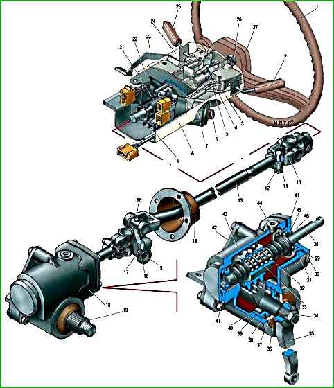
Steering mechanism and steering column: 1 - steering wheel; 2, 25 - steering column switches; 3 - retaining ring; 4 - washer; 5 - bearing; 6 - plastic bearing bushing; 7 - ignition switch (lock); 8 - lower part of the steering column casing; 9 - steering column shaft; 10 - cardan joint; 11 - wedge; 12 - nut; 13 - intermediate steering shaft; 14 - intermediate shaft seal; 15 - cardan joint bearing; 16 - bearing needles; 17 - retaining ring; 18 - steering mechanism; 19 - bipod shaft; 20 - universal joint grease nipple; 21 - steering column pipe; 22 - bracket; 23 - handle of the steering column fixation mechanism; 24 - upper part of the steering column casing; 26 - steering wheel fastening nut; 27 - decorative steering wheel trim; 28 - ball nut screw; 29 - top cover; 30 - adjusting gasket; 31, 39 - sealing rings; 32 - ball nut; 33 - ball nut; 34 - nut; 35 - bipod; 36 - cover; 37 - foam ring; 38 - retaining ring; 40 - bipod shaft bearing; 41 - ball nut screw bearing; 42 - bracket; 43 - crankcase; 44 - filler plug; 45 - oil seal; 46 - protective cover
- - turn the steering wheel 2.5 turns from the straight-line position in any direction;
- - swing the steering gear screw by the fixed fork by hand; if the screw has axial or radial movement (play of the fork relative to the steering mechanism cover), then the screw bearings must be adjusted.
Adjustment is carried out in the following sequence:
- . disconnect bipod 18 and steering wheel shaft fork 12;
- . unscrew the bolts securing the steering mechanism to the bracket and remove the steering mechanism from the car;
- . drain the oil through the hole closed by plug 4;
- . remove two plugs 20 on the crankcase;
- . remove two covers 17 and 19 and sponge seal 16 of the sector shaft;
- . remove retaining ring 14;
- . straighten the grooves on the bearings of the sector shaft with a beard and remove them with a puller, eliminating impacts and distortions on the bearing;
- . remove shaft sector 3;
- . unscrew the bolts securing the upper crankcase cover, remove the cover and remove one of the adjusting shims 5;
- . Reinstall the crankcase cover and check the torque of the screw in the bearings.
The torque should be 0.4-0.8 Nm. In this case, no play of the screw should be felt;
- . install sector shaft 3 and bearings, lubricating the seating surfaces and sealing rings with steering oil.
When installed, the bearings should be directed with eccentricity downwards (the sector shaft is as far away from the ball nut as possible).
Distortions during assembly are not allowed.
Seizing of bearings on the sector shaft or crankcase indicates misalignment or incorrect orientation of the bearing eccentricities;
- . adjust the engagement in the nut-sector pair;
- . secure the sector shaft bearings from rotation by bending the shoulder on the bearings into the holes on the crankcase;
- . reassemble the steering mechanism in reverse order;
- . install the steering mechanism on the car;
- . add oil;
- . install bipod 18 and shaft fork 12 (when installing wedge 10, nut 6 and washers should be on the side of the machined end on fork 8).
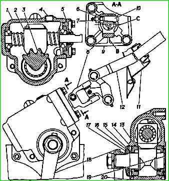
Adjusted connection between the nut and the steering gear sector
The clearance in the engagement of the working pair is considered acceptable if the play at the lower end of the bipod when the wheels are positioned for straight movement with the propeller bearings adjusted is no more than 0.3 mm.
If the play exceeds this value, then it is necessary to adjust the engagement of the nut-sector pair, since operating a vehicle with excessive play leads to failure of the steering mechanism.
The sequence of operations for checking pair engagement is as follows:
- - put the wheels in the straight-line driving position and, by turning the steering wheel, align the mark “C” on the end of the screw with the edge “B” of the top cover 9 (the mark “O” should be at the bottom);
- - disconnect the longitudinal steering rod from the bipod;
- - shaking the bipod with your hand, determine the play at its end (the axial play of the screw should not be felt).
If the bipod play is more than 0.3 mm, adjust the pair engagement in the following order:
- . remove the steering mechanism from the car;
- . remove two plugs 20 on the crankcase in the area of the sector shaft;
- . disconnect the bipod 18, remove the two covers 17 and 19 and the sponge seal 16 of the sector shaft;
- . straighten the grooves on the bearings of the sector shaft 3 with a beard;
- . adjust the engagement of the nut with the sector by simultaneously turning the outer rings 15 in the crankcase holes clockwise from the side of the spline on the sector shaft.
When adjusting, exclude the possibility of distortions of the sector shaft in the outer rings (incorrect orientation of bearing eccentricities).
The torque of the screw on the adjusted mechanism should be 1-1.8 N:
- - secure the sector shaft bearings from turning by bending the shoulder on the bearings into the holes on the crankcase;
- - re-check the torque of the screw and the play at the end of the steering bipod;
- - install two plugs 20 on the crankcase, sponge seal 16 of the sector shaft (lubricating it and the sector shaft underneath with grease), two covers 17 and 19 and bipod 18;
- - install the steering mechanism on the car;
- - connect the longitudinal steering rod to the bipod and pin the pin.
On new steering mechanisms, the torque of the screw has been increased (to compensate for the running-in of parts) to 1.8±0.35 Nm.
If it is necessary to adjust the column fixing mechanism, you must:
- - remove the lower casing 8 by unscrewing two screws and freeing it from the lower clamp;
- - remove the upper casing 24, bringing the column as close as possible to the driver;
- - loosen the lock nut and tighten the bolt to a torque of 9.0-12.5 Nm (0.9-1.25 kgf/m);
- - fix the locknut with a torque of 14-18 Nm (1.4-1.8 kg/m), preventing the bolt from unscrewing;
- - check column fixation;
- - install the upper and lower casings.
Let's look at the adjustment in more detail in the pictures
You can adjust the clearance in the propeller bearings on a car, but for subsequent adjustment of the nut-shaft-sector engagement it is more convenient to immediately remove the steering mechanism.

1. Remove the steering mechanism.

2. To avoid damage, remove the plastic cover

3. Remove the foam seal.

4. Using a 13mm head, unscrew the four bolts securing the upper cover of the mechanism housing

5. Using a screwdriver, remove the cover

6. Remove one of the shims.
Install the cover, tighten the bolts and check the play.
If there is play, remove another gasket.
Having achieved the absence of play, we adjust the gap in the engagement of the nut-shaft-sector pair.
To do this, install the bipod on the shaft and, slightly tightening its nut, turn the screw to move the bipod to the middle position, after which we rock the sector shaft by the bipod.
The stroke of the bipod end should not be felt (exceed 0.3 mm).

7. If it is larger, then using an awl or a thin screwdriver, remove the plastic cover

8. We take out two plugs.

9. Use pliers to remove the spring rings on both sides of the mechanism body.

10. Using a thin beard with a blunt end, we straighten the holes on the edge of the outer ring of the sector shaft bearings

Using a special wrench, turn the eccentric outer rings of the bearings in the crankcase holes clockwise from the side of the splined end of the sector shaft.
When adjusting, the possibility of misalignment of the sector shaft should be excluded, for which we turn both bearings alternately at a small angle until the gaps in the engagement are eliminated.
The torque of the screw on the adjusted mechanism should be 10–18 kgf.cm.
Secure the eccentric rings from turning by bending their collars into the crankcase holes with a bead.
Assemble the steering mechanism in reverse order and install it on the car.
When assembling, we moisten the foam rubber seal of the shaft-sector with transmission oil, and the spline joint with SHRUS-4 or ShRB-4 grease.
")

")
")
")
")
")
")
")