Ural car
The Ural all-terrain vehicle boasts excellent technical and economic performance, reliability, durability, and ease of maintenance. It operates successfully in a wide range of road and climate conditions, including the Far North and Western Siberia, the sandy terrain of Central Asia, and the humid subtropics.
The Ural-375D all-terrain vehicle, with a 6x6 wheel arrangement, is designed for transporting cargo, people, and towing trailers on all types of roads and terrain.
The Ural-375D is based on the Ural-375D and is available in 6x6 versions: the Ural-375DYU, -375K, -375SK1, -376N, and -375SN.
The Ural-377, with a 6x4 wheel arrangement, is designed for transporting cargo on all types of roads with a single axle load of 6 tons.
The Ural-377 features a non-driven front axle, a ZIL-375Ya4 engine, a platform with three drop sides and a metal base, and a horizontal spare tire carrier. This vehicle does not have a tire pressure regulation system, its components are not sealed, there is no winch, and no power take-off (PTO).
The Ural-377 is based on the Ural-377 and is available in 6x4 configurations: the Ural-577N, -377SN, and -377S.
The Ural-377N uses wide-profile tires.
The Ural-377S and -377SN tractor units are designed for towing semi-trailers on paved roads and unpaved roads in good condition. The tractor units differ in tires and axle gear ratios.
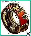
The service brakes are disassembled during maintenance and troubleshooting (oiling, wear and tear of brake shoe linings, wear or damage of wheel cylinder sealing cuffs, breakage of the tension spring, etc.).
- Car parking brake repair Ural
- Auxiliary brake ("mountain" brake) of the car Ural
- How to repair the pneumatic brake booster car Ural
- Design + repair + operation of the Ural car winch
- Ural tire pressure control system
- Fifth wheel coupling of the car Ural
- The design of the Ural car power take-off
- Design + repair + adjustment of the transfer case of the Ural car
- Ural car engine
- How to repair the clutch car Ural
")

")
")
")
")
")
")
")