Removing and checking the GAZ-3110 steering mechanism
Place the car on the parking brake
Install stands for the rear wheels.
Loosen the front left wheel bolts.
Raise and place the front part of the car on supports.
Unscrew the bolts and remove the wheel.
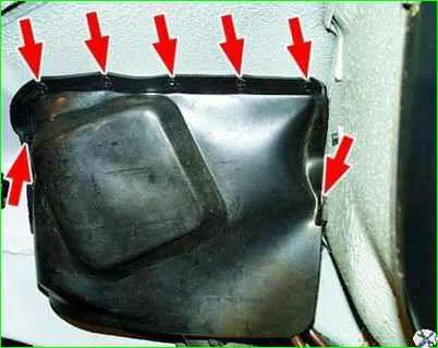
From the side of the wheel well, remove the mudguard from the left wheel by using a screwdriver to pry off the caps securing it.
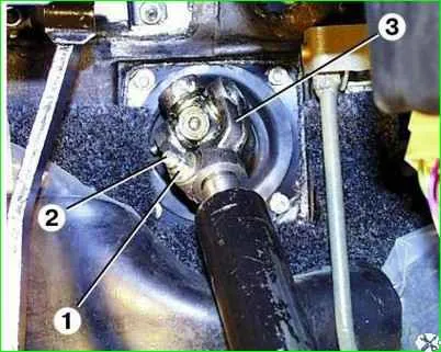
From inside the passenger compartment, unscrew the fastening nut 1, remove the wedge 2 and disconnect the worm shaft of the steering mechanism from the cardan joint 3.
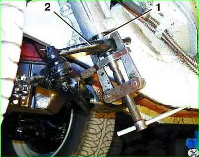
Having previously marked the relative position of the bipod shaft 1 and the steering bipod 2, unscrew the fastening nut and press the bipod off the shaft.
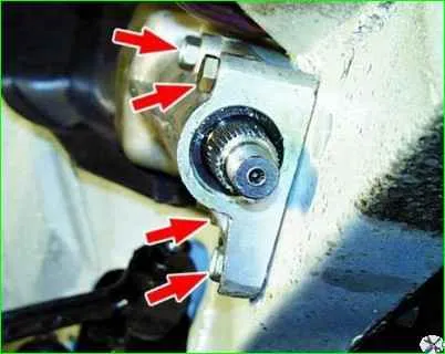
Unscrew the four mounting bolts and remove the steering mechanism.
It is recommended to mark the bolts, since they are of different lengths.
Disassembling the steering mechanism
Clean the steering gear housing from dirt.
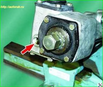
Drain the oil from the steering gear housing through the filler hole by unscrewing the plug.
It is advisable to do this immediately after the trip.
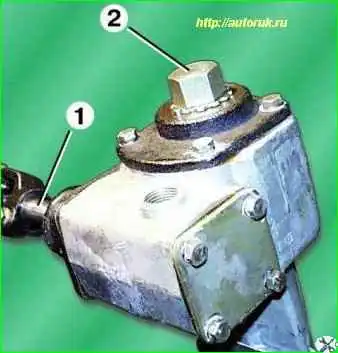
Clamp the steering gear housing in a vice by the boss to secure the housing to the body and set the roller to the middle position by turning its shaft 1.
Unscrew cap nut 2.
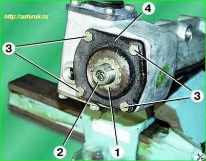
Remove lock washer 1 with gasket.
Unscrew adjusting screw 2.
Unscrew the four fastening bolts 3 and remove the side cover 4 with the bipod shaft assembly and gasket.
Before removing the bipod shaft, thoroughly clean its lower end to prevent dirt from getting into the crankcase.
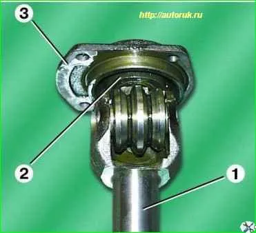
Remove side cover 3 from bipod shaft 1 together with bearing 2.
If necessary, press the bearing out of the side cover.
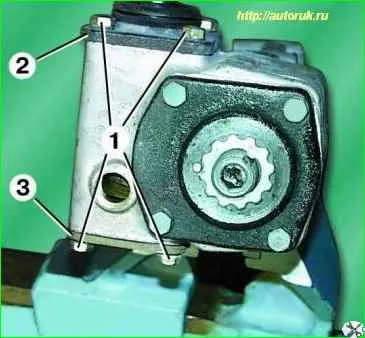
Unscrew four bolts 1 each securing the upper 2 and lower 3 crankcase covers and remove the covers together with the shim packs.
Remove the worm along with the roller bearings from the crankcase.
If necessary, remove the oil seals from the crankcase and the top cover.
Inspection of the steering mechanism
Check the steering gear housing. If cracks or chips are found, the crankcase must be replaced.
If wear is detected on the bipod shaft bushings (the shaft has lateral play), it is necessary to replace the bushings or the crankcase with bushings assembly.
Check the worm and roller.
If any chipping, cracks or dents are found, replace defective parts.
The bearings of the bipod shaft and the worm with the shaft should not have pitting, cavities or visible wear on the rolling surfaces.
If traces of oil leakage were noticed during operation, it is necessary to replace the oil seals installed in the crankcase and the top cover.
Assembling the steering mechanism
The steering mechanism is assembled in the reverse order of disassembly.
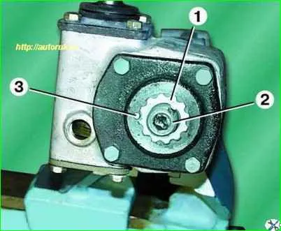
Insert lock washer 1 with its protrusion into the groove of adjusting screw 2, thereby securing the screw.
The lock washer itself is fixed with pin 3. Axial play of the worm is unacceptable.
Elimination of play is carried out by selecting the thickness of the package of adjusting shims under the front crankcase cover, which ensures preload of the bearings.
In this case, the torque of turning the worm shaft should be in the range of 0.4–0.8 Nm (0.04–0.08 kgf m).
Pour 0.4 liters of TM-5-18 or Omskoil Super T oil into the crankcase.
Installation
Install the steering mechanism in the reverse order of removal.
In this case, the nuts securing the mechanism to the spar are tightened with a torque of 50–60 N m (5.0–6.0 kgf m).
The bipod must be installed on the shaft in accordance with the marks.
When connecting the worm shaft to the cardan bearing, the front wheels and steering wheel must be set to the position where the vehicle is moving in a straight line.
After installation, adjust the mechanism.
Adjusting the steering mechanism
Set the steering wheel to the position where the vehicle is moving in a straight line. In this case, the engine must be turned off.
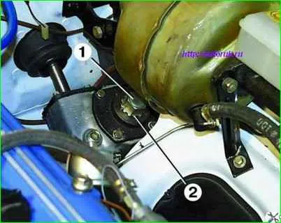
Unscrew cap nut 1 and remove lock washer 2.
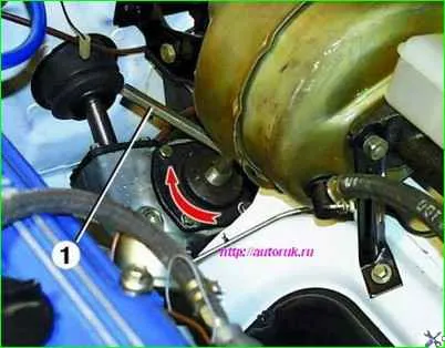
Slightly turn the adjusting bolt clockwise using hexagon 1 to ensure that the free play of the steering wheel does not exceed 17 mm.
The amount of free play is measured on the wheel rim.
After adjustment, fill the hexagonal cavity of the adjusting bolt with Litol-24 lubricant.
Install the lock washer with its protrusion into the groove of the adjusting screw and tighten the cap nut.
Make a test drive and check that the steering mechanism is adjusted correctly while driving.
If the front wheels are sluggish when exiting a turn, you need to unscrew (counterclockwise) the adjusting bolt 1-2 slots into the lock washer and adjust the steering mechanism again.
If it is impossible to achieve the required result, the steering mechanism must be repaired or replaced.


