Ignition coil of ZMZ-406 GAZ-3110 engine
Ignition coils are designed to generate high voltage electric current to ignite the working mixture in the engine cylinders
Ignition coils (2 pcs.) are installed on top of the engine.
The ignition coil structure is shown in the figure.
The ignition coil is a transformer.
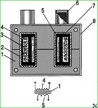
The primary winding 5 is wound on the magnetic core 1, and the secondary winding 3 is wound on top of it in sections.
The windings are enclosed in a plastic housing 2. The space between the windings is filled with compound 7.
The housing has low and high voltage terminals 6.
Low voltage electrical impulses enter the ignition coil from the control unit.
In the ignition coil they are transformed into high-voltage electrical impulses, which are transmitted through wires to the spark plugs.
Electric discharge occurs simultaneously in two spark plugs of the first and fourth cylinders or the second and third cylinders.
For example, one electrical discharge occurs in the spark plug of the first cylinder when the compression stroke ends there; the second discharge occurs in the spark plug of the fourth cylinder when the exhaust stroke occurs there.
The electric discharge in the spark plug of the fourth cylinder during the exhaust stroke does not affect engine operation.
With further rotation of the crankshaft, an electric discharge will occur in the spark plug of the fourth cylinder.
If oil gets on the wires, they should be wiped with a rag soaked in gasoline.
If necessary, check the serviceability of the current-carrying wire with an ohmmeter.
The resistance of the wires to the 1st and 2nd cylinders should be no more than 1000 Ohms, and the resistance of the wires to the 3rd and 4th cylinders should be no more than 900 Ohms.
Removing the ignition coil
Disconnect the wire from the negative terminal of the battery.
Disconnect the 4 blocks 1 low-voltage wires and high-voltage wires 5 from the coil.
Unscrew bolts 2, remove bar 3 and coil 4.
Remove the second coil in the same way.
Checking the ignition coil

Coils 30.3705 and 301.3705 are checked with a spark plug diagnostician 1AP975000 on a car.
To do this, disconnect the high-voltage wires from the coil and connect the diagnostician instead.
Then crank the engine with the starter, and a spark should appear in the diagnostic spark gap in time with the operation of the cylinders.
Checking and replacing the ignition coil on the ZMZ-406 engine
Turn off the ignition and disconnect the negative terminal of the battery.

Disconnect the two blocks from the connectors of the primary winding of the ignition coil.

Disconnect the high-voltage wires from the connectors of the secondary winding of the ignition coil.
Connect an ohmmeter to the terminals of the primary winding of the coil and measure its resistance.

A working coil should have a primary winding resistance in the range of 0.4–0.5 Ohms.

To obtain an accurate measurement value, by short-circuiting the voltmeter probes, we measure the resistance of the device wires.

Connect an ohmmeter to the high-voltage terminals and measure the resistance of the secondary winding of the coil.
A working coil should have a secondary winding resistance of 5–7 kOhm.
You can more accurately check the serviceability of the coil only on a special stand.
A working coil should develop a secondary voltage of at least 24 kV, a spark energy of 50 mJ with a duration of 1.5 ms at an input signal frequency of 50 Hz.
We replace the faulty ignition coil.

Having disconnected the wires, use a 12mm wrench to unscrew the two bolts securing the coil to the cylinder head cover and remove it.

Install the coil and connect the wires to it in the reverse order.
Ignition coils for the ZMZ-405 engine
Ignition coils ZS-K-1x1 0 221 504 027 Bosch (40904.3705000*) or similar, individual, four, transformer type, mounted on the valve cover.

Designed to generate high voltage energy to spark plugs.
")

")
")
")
")
")
")
")