Replacing the rubber bushings of the lower arms of the GAZ-3110
Install the car on a lift or inspection ditch
Clean the places where the levers are attached from dirt.
Loosen the wheel mounting bolts.
If the car is parked in a ditch, then put the car on the parking brake, put chocks under the rear wheels, lift the front of the car and place it on supports.
Remove the wheel. Place a jack (preferably hydraulic) under the spring cup and, using it to lift the cup, load the spring.
If the car is installed on a lift, first remove the wheel, and then place a stable support under the spring cup and, carefully lowering the car, load the spring.
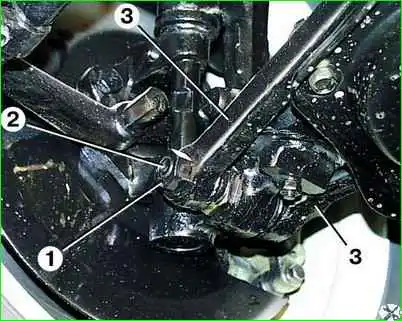
Unscrew nut 1, remove pin 2 and disconnect lower arms 3 from the rack.
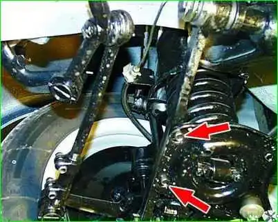
Unscrew the two bolts securing the spring cup to the lever.
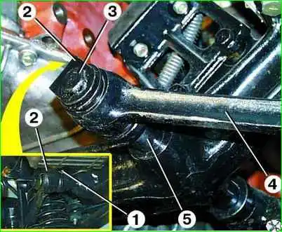
Unscrew bolt 1 of the fastening and remove bracket 2 of the axle pins. Unscrew pin 3 of the axle from bushing 5 of the beam and remove the lever.
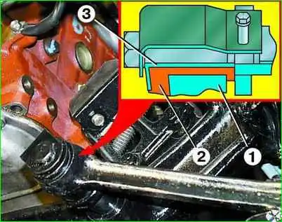
Remove or, if necessary, press the pin out of the lever. In this case, it is possible that the spacer sleeve 3 will remain on the pin.
In this case, the spacer sleeve must be removed from the pin by sawing it or carefully cutting it off with a chisel.
Clamp lever 1 in a vice and press rubber bushing 2 out of it.
Carefully clean the lever eye from dirt and, possibly, remnants of the old bushing.
After soaking the new bushing in unleaded gasoline, insert the spacer into it.
Press the rubber bushing assembly with the spacer into the lever eye using a mandrel.
Inspect the seat of the lever on the finger and, if necessary, clean the surface of the finger with fine sandpaper.
Insert the finger into the bushing of the assembled lever.
Let's take a closer look at removing the levers and replacing the rubber bushings
We jack up the front of the car, place a stop under the spring cup and lower the car, compressing the spring.
The upper buffer should move away from the stop.
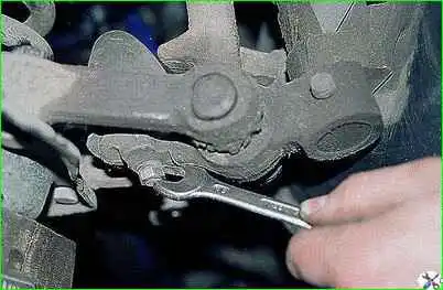
Use a 13mm wrench to unscrew the nut.
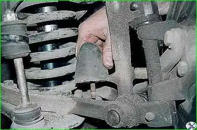
Remove the lower buffer.
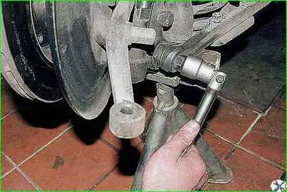
Use a 22 mm socket to unscrew the nut and remove the lower pin of the strut.
Retract the stand.
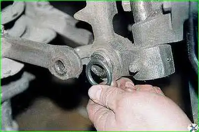
Remove the rubber protective ring of the threaded joint.
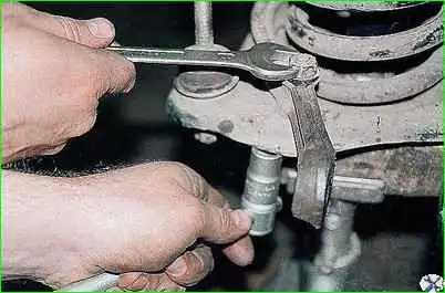
Holding the bolts securing the lever to the spring cup with a 14mm socket, with a 17mm wrench, unscrew the two nuts and disconnect the lever from the cup
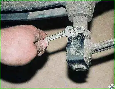
Use a 10mm wrench to unscrew the bolt
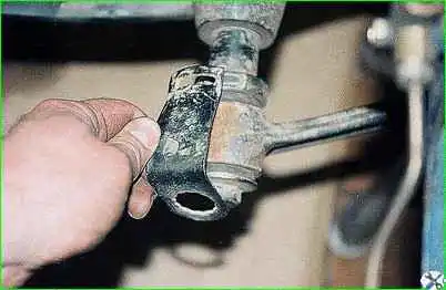
Remove the locking plate.
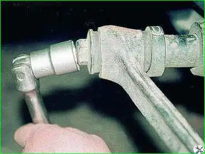
Use a 22mm head to turn off the finger
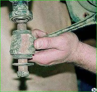
Remove the lower suspension arm.
Remove the second lever in the same way
Replacing rubber bushings
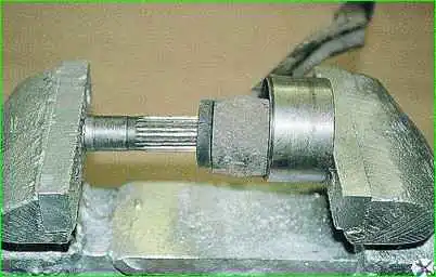
Using a vice, through a mandrel, squeeze the spacer sleeve out of the rubber bushing.
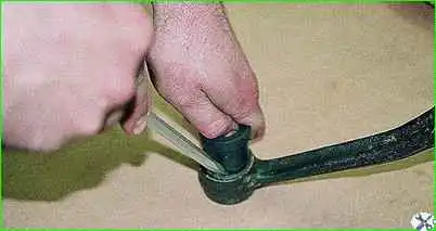
Then we squeeze the rubber bushing out of the lever in the same way.
Wet the new bushing with gasoline or WD-40 and use a blunt flat-head screwdriver to insert its edge into the hole in the lever.
Pressing by hand, we finally press the rubber bushing into the lever.
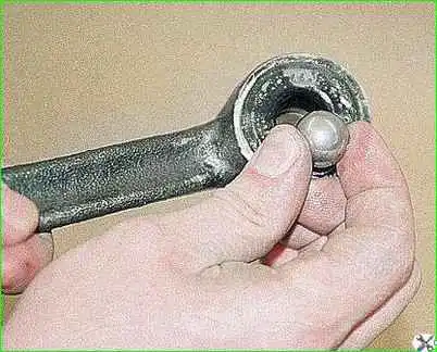
We also press in the spacer sleeve.
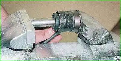
This is easier to do by inserting a steel ball of slightly larger diameter into the hole in front of the spacer
Then installation work should be carried out in the reverse order of disassembly.
It should be borne in mind that the final tightening of the threaded connections securing the lever is carried out only on the suspension in a loaded state.
Tightening torques:
- - lever fingers - 180-200 Nm (18.0-20.0 kg/cm),
- - finger nut - 120-200 Nm (12.0-20.0 kg/cm).
Replacement of the rubber bushing of another lever on the same side of the suspension is carried out in the same way after installing the previous lever in place.
Check the alignment of the front wheel angles. (GAZ-3110 wheel alignment)


