The cardan transmission used in the vehicle consists of two shafts - intermediate 2 (Fig. Cardan transmission) and rear axle 7, as well as intermediate support 5 with bearing 22
The cardan shafts are connected to each other by a cardan joint.
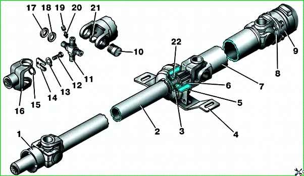
Cardan transmission: 1 - sliding fork; 2 - intermediate cardan shaft; 3 - intermediate cardan shaft; 4 - engine support bracket; 5 - intermediate propeller shaft; 6 - deflector; 7 - rear axle propeller shaft; 8 - propeller shaft flange; 9 - final drive pinion flange; 10 - crosspiece needle bearing; 11 - crosspiece; 12 - tie bolt; 13 - lock washer; 14 - lock plate; 15 - sealing ring; 16 - splined fork; 17 - sealing cuff; 18 - deflector; 19 - protective cap; 20 - grease nipple; 21 - locking ring; 22 - intermediate support bearing
Maximum permissible dimensions, mm:
- radial play of crosspiece bearings 0.1
- runout of cardan shaft pipe 0.3
- runout of landing belt of flange of driving gear 0.15
- runout of secondary shaft of gearbox 0.15
Removing the cardan transmission
Install the car on an inspection pit or lift.
Clean the threaded connections of the cardan transmission mount from dust and dirt.

Unscrew the two nuts 1 securing the intermediate support bracket to the body, two bolts 2 securing the bracket to the intermediate support 4 and remove the bracket 3.

Unscrew the four bolts securing the cardan shaft to the flange of the rear drive pinion bridge, having previously marked the relative positions of the flanges.
Remove the cardan transmission.
If it is difficult to separate the flange of the rear cardan shaft from the flange of the rear axle pinion, it is permissible to apply light blows with a soft metal hammer to the flange of the rear cardan shaft (but under no circumstances to the cardan bearing).
To prevent oil from leaking from the gearbox, insert a plug into the extension of the rear gearbox housing.
Disassembling the cardan transmission
Mark the relative positions of the shafts, sliding fork and flange of the rear cardan shaft.

Bend back the edges of the lock washer 2 and loosen the bolt 1 so that the U-shaped plate 3 can be removed.

Disconnect the cardan shafts. Press out intermediate support 1 together with shaft bearing.
Disassembling universal joint
Clean universal joint from dust and dirt.
Mark mutual arrangement of universal joint forks.

Remove crosspiece bearing retaining rings.

Press out two opposite crosspiece bearings from the lugs at the same time (press one bearing outward and the other one inward of the fork) and remove them.
When pressing out, make sure that the tool used as a mandrel does not damage the grease nipple screwed into the crosspiece.
Similarly, press out the second pair of crosspiece bearings, remove the bearings, sealing cuffs, mud deflectors and the crosspiece.
Inspection and defect detection of cardan transmission parts
Clean the units and cardan transmission parts.
The cardan shafts must not have any signs of deformation.
Breakage of the bearing needles, traces of the needles being pressed into the bearing housing and into the crosspiece journal are not allowed.
The crosspiece oil channels must be clean.
The sealing cuff must It must be elastic and flexible, and must not have cracks or breaks.
Traces of oil leakage through the sealing cuff during the maintenance operation of adding grease to the bearing cavities are not a defect.
The grease nipple must ensure unimpeded access of oil to the crosspiece bearings when adding grease during operation.
Oil must not leak from the bearing cavities through the grease nipple.
The intermediate support bearing must rotate easily and have no chipping, pitting, cavities, or tarnish on the rolling surfaces.
The rubber part of the intermediate support must be elastic and free of cracks and breaks. Vulcanized parts should not have any signs of tearing.
Fasteners should not have any thread defects.
If upon inspection it is found that the units and parts do not meet the requirements stated above, they must be replaced.
Assembling the universal joint
Before installing new needle bearings, the cups and needles must be cleaned of preservative grease.
This operation is carried out for each bearing separately, eliminating the possibility of mixing needles from different bearings.
Fill the cup with transmission oil up to half the volume and insert the needles into the cup.
Clean the new crosspiece from preservative grease (including the channels) and screw the grease nipple into the threaded hole.

Put the sealing cuffs 1 and mud deflectors 2 on the crosspiece journals.
Insert the assembled crosspiece inside the universal joint fork so that after assembling the cardan transmission, the grease nipples of each universal joint are located on the same side.
Insert the bearing with needles into the fork eye and insert the crosspiece journal into the bearing.
Preliminarily press the installed bearing into the eye, while simultaneously holding the inserted crosspiece from falling out.
Insert into the opposite the second bearing into the eye, aligning the bearing hole and the crosspiece journal, and press it into the eye, while simultaneously turning the crosspiece on the bearings.

Finally press in the first bearing so that the grooves for the retaining rings are located at an equal distance "a" relative to the inner ends of the fork.
Insert the retaining rings into the bearing grooves, orienting their antennae inside the fork.
Introduce the free crosspiece journals into the other fork.
Check the ease of movement of the fork in different planes.
Assembling the cardan transmission
Assembly of the cardan transmission is carried out in the reverse order of disassembly, in accordance with the previously made marks.
Installation of the cardan transmission is carried out in the reverse order of removal, in accordance with the previously made marks.
Tighten the bolts securing the cardan transmission flange to the flange of the main gear pinion with a torque of 27–30 N m (2.7–3.0 kgf m).
Nominal and maximum permissible dimensions and fit of mating parts of the cardan transmission
Table:
- Name of parts - Nominal diameter, mm - Name of mating parts - Nominal diameter, mm:
- Needle bearing - 30 –0.009 - Sliding fork - 30 –0.010 30 –0.034;
- Needle bearing - 30-0.009 - Cardan shaft flange - 30 –0.010 30 –0.034;
- Needle bearing - 16 +0.031 16 +0.011 - Bearing seat on cardan shaft crosspiece - 16.3 -0.012;
- Sliding fork - 38 –0.025 38 –0.050 - Steel-babit bushing - 38+0.0015
Possible malfunctions of the cardan transmission
Vibration of the cardan transmission when driving
Deformation of the cardan shaft pipe - Replace the cardan shaft pipe or repair it in specialized workshops with mandatory dynamic balancing
Loosening of the rear cardan shaft to the rear axle - Tighten the threaded connections
Tearing off the balancing plate from the shaft pipe - Replace the cardan shaft pipe or repair it in specialized workshops with mandatory dynamic balancing
Increased play of the crosspiece in the cardan joint bearings - Replace the bearings and crosspieces of the cardan joint
Increased runout of the seating belt of the flange of the drive gear of the rear axle reducer - Replace the flange
Increased runout of the sliding fork installed in the gearbox - Eliminate the causes of runout of the secondary shaft. Replace the gearbox extension due to wear of the steel-babbitt bushings
Intermediate support bearing defect - Replace the bearing
Intermediate support fastening to the bracket or the bracket to the underbody is loose - Tighten the threaded connections
")

")
")
")
")
")
")
")