Removal and installation of the crankshaft of the ZMZ-402 engine
Remove the oil sump and crankcase gasket
Remove the oil pump.
Remove the fan drive belt.
Remove the generator drive belt.
Remove the timing sprocket cover.
Install the piston of the 1st cylinder in the idle position. compression stroke.
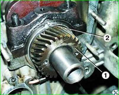
Use a puller to press sprocket 1 from the end of the crankshaft.
Remove thrust washer 2.
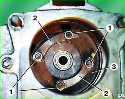
Unscrew the four nuts 1, having previously bent the edges of the locking plates 2, and remove the flywheel 3, removing it from the bottom from the clutch housing.
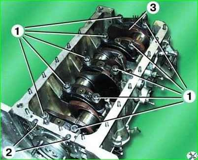
If you do not need to remove the pistons from the cylinders, you do not need to remove the cylinder head; just unscrew the nuts of the connecting rod bolts, remove the connecting rod caps and carefully push the pistons into the cylinders.
Unscrew nuts 1 and bolts 2 and remove the main bearing caps.
Since the lids are tight, knock them off with gentle blows of a hammer.
Remove crankshaft 3 from the main bearing beds. Remove the second thrust washer from the end of the crankshaft.
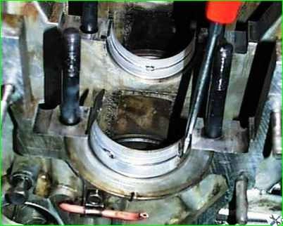
Remove the main bearing shells from the main bearing beds and caps.
It is easier to remove the inserts if you move them with a screwdriver so that the end of the insert protrudes above the edge of the bed.
Defection and repair of the crankshaft
Rinse all parts with gasoline and dry.
Inspect the crankshaft. If it has cracks, it must be replaced.
Unscrew the plugs, clean, rinse with gasoline and blow out the crankshaft oil passages with compressed air.
Tighten the plugs and tighten to a torque of 38–42 Nm (3.8–4.2 kgf m).
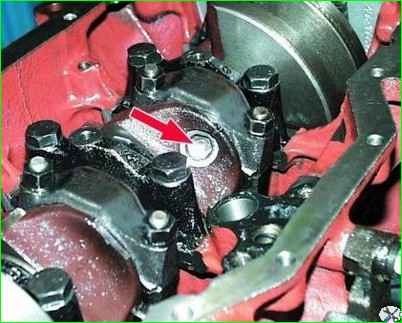
If there are minor marks on the main and connecting rod journals, scratches, burrs, or the ovality of the journals exceeds 0.01 mm, the journals must be ground to the repair size.
After grinding, the necks must be polished. Use an abrasive cone to blunt the sharp edges of the chamfers of the oil channels.
After grinding, wash the shaft and blow out the oil channels with compressed air.
After grinding the crankshaft journals, you need to install main and connecting rod bearing shells of the appropriate repair size.
Inspect the main bearing shells. If they have marks, burrs, scratches, peeling, inclusions of solid particles, etc., replace the liners.
Inspect the flywheel. If the flywheel ring teeth are damaged, there are scuffs, scratches, etc. on the surface adjacent to the clutch driven disc, replace the flywheel. If the flywheel has cracks, it also needs to be replaced.
The primary shaft nose bearing, closed type, is pressed into the hole in the crankshaft on the flywheel side.
Inspect the bearing, if defects are found (large play, seizing, damage to protective rings, etc.), press it out of the crankshaft using a puller.
Press in the new bearing flush with the bottom edge of the chamfer of the hole in the crankshaft.
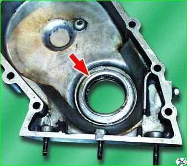
Inspect the crankshaft oil seal in the timing sprocket cover.
If the oil seal is damaged (tears, tears, excessive wear of the working edge, etc.), it must be removed from the cover and a new one pressed in.
If the car has high mileage, it is recommended to replace the oil seal.
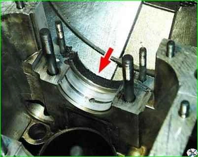
Replace the crankshaft rear seal packing in the main bearing bed and in the holder.
Remove the old packing and insert a new one approximately 120 mm long.
Sawn-off shotgun Place the ends of the stuffing so that it protrudes above the plane of the bed and holder by 0.5–1.0 mm.
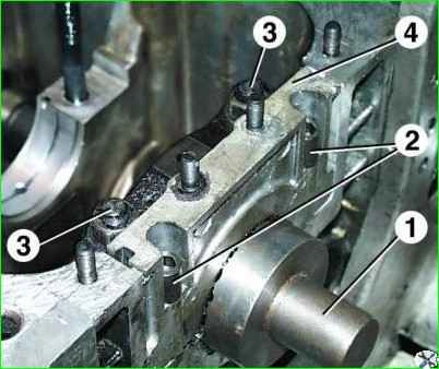
Crimp the packing; to do this, place mandrel 1 in the bearing bed, install holder 4 and the main bearing cover and tighten nuts 3 and bolts 2
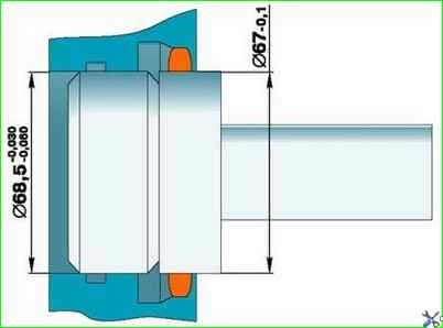
The dimensions of the mandrel are shown in the figure
Check the condition of rubber seals 1 in the packing holder. If they have lost their elasticity, cracked, torn, etc., the seals need to be replaced.
Installing the crankshaft
Before installation, lubricate the crankshaft main and connecting rod journals, main bearing shells and thrust washers with engine oil and place the rear thrust washer on the front end of the crankshaft with an antifriction layer against the crankshaft cheek.
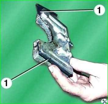
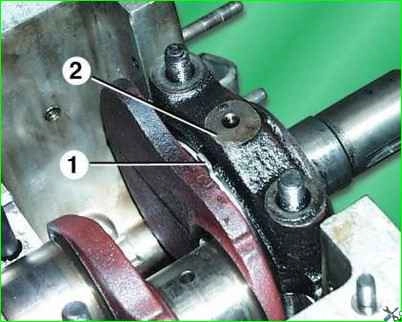
When installing the cover 2 of the first main bearing, the protrusion of the rear thrust washer 1 must fit into the groove of the cover 2.
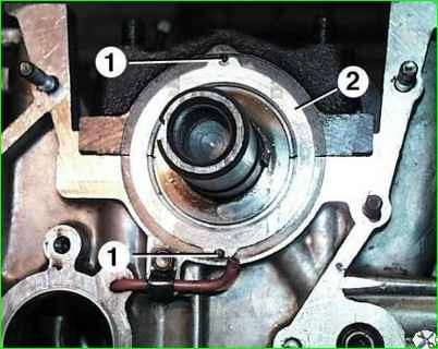
Install the front thrust washer 2 onto the pins 1, with the antifriction layer facing outward.
The spacer between the crankshaft gear and the front thrust washer is installed with a chamfer in the hole towards the thrust washer.
After installing the crankshaft gear, measure its axial clearance, which should be in the range of 0.125 - 0.325 mm.
The gap is measured between the end of the rear thrust washer and the crankshaft cheek, while the shaft must be pressed as far as possible towards the flywheel.
Tighten the nuts of the main bearing caps to a torque of 100–110 Nm (10–11 kgf m), and apply Unigerm-9 sealant to the threads of the nuts.
Tighten the flywheel mounting nuts to a torque of 76–83 Nm (7.6–8.3 kgf m) and lock by bending the edge of the locking plate onto the edge of the nut.
Before attaching the connecting rods, rotate the crankshaft. It should rotate easily, without jamming.


