The car has two independent braking systems: service and parking
The service brake system is hydraulic, dual-circuit (divided into front and rear circuits), with a vacuum booster, pressure regulator and indicator of insufficient brake fluid level in the reservoir.
If one of the circuits of the brake system fails, the second circuit provides braking of the vehicle, although with less efficiency.
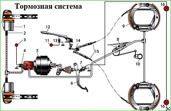
Brake system: 1 – front wheel brake mechanism; 2 – hose; 3 – alarm indicator for emergency drop in brake fluid level; 4 – main brake cylinder; 5 – vacuum booster; 6 – brake pedal; 7 – brake signal switch; 8 – rear wheel brake pressure regulator; 9 – rear wheel brake mechanism; 10 – rear axle axle housing with pressure regulator bracket; 11 – parking brake warning lamp; 12 – parking brake lever; 13 – switch; 14 – equalizer; 15 – cables; 16 – brake signal lamps
The front wheel brakes are disc, with a single-piston floating caliper (when braking, the piston presses the inner pad to the disc, and the caliper, moving in the opposite direction, presses the outer pad).
The minimum permissible thickness of the front brake pads when worn is 3 mm.
The disks are ventilated, mounted on the hubs and secured to them with wheel bolts.
The minimum permissible disc thickness when worn is 19 mm. The bracket is attached with two bolts to the steering knuckle.
The brake cylinder is made in the caliper body; on the outside it is covered with a rubber cover (boot) to protect it from dirt.
Inside the cylinder there is a groove into which an o-ring (cuff) is inserted.
When the piston moves out of the cylinder during braking, this ring twists slightly and after braking ends, it tends to return the piston to its original position.
Due to this, a constant minimum gap between the discs and brake pads is maintained. The cylinder has a bleed valve.
The rear wheel brakes are drum-type, with two-piston wheel cylinders with automatic adjustment of the gap between the shoes and the drum.
Thrust rings are inserted into the cylinder with interference, limiting the free movement of the pistons (after braking is completed), thereby maintaining a constant gap between the pads and the drum.
As the pads wear, the rings shift by the amount of wear.
In the lower hole of the brake pads there are eccentrics for adjusting the position of the pads after replacing them.
The minimum permissible thickness of the rear brake pads when worn is 1 mm.
The maximum permissible internal diameter of the brake drum is 283 mm.
The main brake cylinder is attached to the vacuum booster housing on two studs.
A translucent polyethylene brake reservoir with an insufficient fluid level sensor (in the reservoir cap) is inserted into the holes in the upper part of the cylinder.
In the front part of the cylinder (along the direction of the car) there is a plug screwed in, which serves as a stop for the return spring and is sealed with a copper gasket.
The pistons in the master cylinder are arranged in series, the one closest to the vacuum booster operates the rear brakes, the other piston operates the front ones.
The rubber sealing rings (cuffs) of the master brake cylinder are asymmetrical in cross-section, so it is important to orient them correctly during assembly.
When disassembling the cylinder, it is recommended to replace the cuffs regardless of their condition.
When installing the master cylinder on a vehicle, check the gap (1.35–1.65 mm) between the end surface of the vacuum booster housing and the adjusting bolt.
If the gap value differs from the specified value, unscrew the lock nut and, by rotating the adjusting bolt, achieve the desired gap, then tighten the lock nut.
The vacuum booster is located between the pedal assembly and the main brake cylinder and is attached to the bracket with four studs.
The amplifier is of a non-separable design; if it fails, it is replaced.
The simplest check of its serviceability is as follows: on a car with the engine turned off, press the brake pedal several times and, holding the pedal pressed, start the engine.
If the amplifier is working properly, after starting the engine the pedal should “move” forward.
Failure to operate or insufficient efficiency of the vacuum booster may be caused by a leak in the vacuum hose from the intake manifold.
The pressure regulator is attached with two bolts to a bracket in the rear of the body.
It prevents the rear wheels from locking earlier than the front wheels, which increases the vehicle's directional stability when possible.
Reacting through a load spring to the loading of the rear axle, it limits the fluid pressure in the rear brake circuit. The regulator cannot be repaired; if it fails, it must be replaced.
After replacing the adjuster or rear suspension components, it is necessary to readjust the position of the load spring relative to the rear axle.
Parking brake system drive – mechanical, cable, to the rear wheels.
It consists of a lever (with a handle and a locking mechanism), an intermediate lever and its rod, an equalizer and its rod, cables, a drive lever with a rod in the rear brake mechanisms.
The free play of the drive lever is adjusted by an eccentric on the rear block, and the tension of the cables is adjusted by an adjusting nut on the equalizer rod
What are the brake malfunctions of the GAZ-3110 car:
- - increased brake pedal travel;
- - the rear brake drum heats up;
- - spontaneous braking of the car;
- - different operation of the brake mechanisms of one axle;
- - excessive force when pressing the pedal;
- - weak action of the parking brake drive.
Let's take a closer look at what causes these problems:
Increased brake pedal travel
Brake fluid leakage from the brake system hydraulic drive - Identify the cause of the leakage and eliminate it by tightening the threaded connections or replace damaged parts. Bleed the brake system
Defective cuffs of the main brake cylinder - Replace the defective cuffs
Presence of air in the brake system due to the formation of an emulsion (overheating of the brakes) - Replace the brake fluid and bleed the brake system
Wear of the friction linings of the brake pads of the front and rear brakes. The remaining thickness of the brake pads is less than the maximum permissible values - Replace the brake pads
The rear brake drum gets hot due to spontaneous braking of the wheel
Loose or broken tension spring of pads - Replace tension spring
No guaranteed clearance between the friction linings of the brake pads and the working surface of the brake drum - Adjust the parking brake drive
The front brake drum gets hot due to spontaneous braking of the wheel
Piston jamming due to contamination or corrosion in the caliper cylinder - Clean the cylinder and piston from dirt or corrosion. If necessary, replace the bracket housing assembly
Spontaneous braking of the car
Incorrect adjustment of the vacuum booster - Adjust the vacuum booster
The hole in the master cylinder reservoir cap is clogged - Clean the hole
Incomplete return of the brake pedal after removing the load from it - Clean the pedal assembly from dust and dirt. Check the plastic bushings and return spring and replace if necessary
Swelling of the master cylinder cuffs or wheel cylinders - Replace the defective cuffs. Bleed the brake system by filling it with the recommended brake fluid
The compensation holes of the main brake cylinder are clogged - Clean the compensation holes
Different operation of the brake mechanisms of one axle (the car pulls to the side when braking)
Oiling of the friction linings of the brake mechanisms - Eliminate the causes of oil getting into the brake mechanism.
Wash or replace oily pads
Scuffs on the working surface of the rear brake drum - Clean the damaged areas. If necessary, bore, grind or replace the drum
The pressure regulator is incorrectly adjusted. The rear wheels lock before the front ones - Adjust the pressure regulator
When braking, excessive force is required when pressing the pedal
The vacuum brake booster is faulty - Replace the vacuum booster
Piston jamming in the cylinder due to contamination or corrosion in the bracket cylinder - Clean the cylinder and piston from dirt or corrosion. If necessary, replace the bracket housing assembly
Oiling of the working surfaces of the brake mechanism - Eliminate the reasons for oil getting into the brake mechanism. Wash or replace oily pads
Weak action of the parking brake drive
Wear of rear brake pads - Adjust the parking brake system drive
Training the parking brake system drive cables - Adjust the tension of the cables. If necessary, replace the cables
")

")
")
")
")
")
")
")