Exterior lighting devices include: headlights, front, rear and side marker lights, license plate lights, ground light (door step), rear fog lights, rear reflectors
The headlights have halogen dual-filament lamps AKG12-60+55. 60 W filament - high beam, 55 W filament - low beam.
The headlights are turned on by the central light switch, turned to the third position.
Attention! When installing a halogen lamp in a headlight, do not touch the bulb with your fingers to avoid a decrease in the luminous flux or destruction of the bulb during operation.
Headlights are adjusted with the engine off at a special post equipped with a work platform, a flat screen with a matte coating, a lux meter with a photo receiver and a device that orients the relative position of the bus and the screen.
Two adjustment screws are located behind the headlight rim on the right and left. The vertical adjustment is made by simultaneously rotating both screws in one direction, and the horizontal adjustment is made by rotating the screws in opposite directions.
To adjust the headlights, do the following:
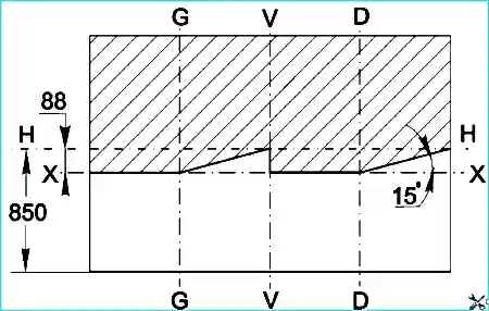
Place the bus in running order (with normal tire pressure) at a distance of 5 meters from the screen, on which the markings are made in accordance with the attached figure.
Remove the headlight bezels by unscrewing the screw that secures them.
Turn on the low beam and, closing one of the headlights, adjust the other with the adjusting screws so that the cut-off line of the low beam is positioned as shown in the figure.
Then, adjust the second headlight in the same way.
The upper edge of the light spots of the adjusted headlights should be aligned with the X-X line (see Fig. 1), and the intersection points of the horizontal and inclined sections of the cut-off line should be aligned with the G-G and D-D lines.
The license plate lights (lamps AC 12-5) are switched on by the central light switch.
The ground lighting lamp (lamps A 12-21-3) is installed under casing covering the passenger door opening mechanism.
They are switched on when the central light switch and the limit switch included in the door drive mechanism are on.
The rear fog lights (lamps A 12-21-3) are switched on by the switch on the instrument panel when the low beam headlights are on.
The control lamp built into the switch signals that they are on.
When switching to the "High beam" or "Parking lights on" modes, the rear fog lights go out.
Fog lights should only be used when driving in fog or in other conditions of poor visibility.
Connecting fog lights in parallel with the "brake light" lights is prohibited.
The interior lighting devices include the interior lamps (lamp A 12-21-3), driver's lamp (lamp A 12-10), instrument panel lighting lamps AMN 12-3
Maintenance of the lighting system consists of checking its serviceability during daily technical inspection and performing work provided for in the list of technical maintenance works.
External signaling includes direction indicators and hazard warning lights, side repeaters of direction indicators, side lights, brake lights and reversing lights, electric horns.
Direction indicators and hazard warning lights
The bus is equipped with an electronic interrupter of direction indicators and hazard warning lights, which also ensures monitoring of the serviceability of the signal lamps.
If, when the direction indicators are turned on, the direction indicator lamp flashes at double frequency, this indicates a malfunction of the lamp of one of the direction indicators on the right or left side of the bus (lack of contact or burnout).
If, when the turn signals are turned on, there is a single light signal from the indicator lights, this is a consequence of a short circuit to ground in the contacts of the light or the supply wiring.
If the turn signal lamp does not light, but the turn signal lamps are in good condition, then it is necessary to check the serviceability of the signal lamp.
If, when the turn signals are turned on, their lamps and the signal lamp do not light, this means that the fuse or breaker of the turn signals (or its circuit) is faulty.
The emergency flashing signal system simultaneously turns on all the turn signals in flashing mode, warning the vehicles in front and behind about the malfunction of the bus in order to avoid an emergency situation.
The signal system consists of an emergency switch alarm, turn signal flasher relay and turn signal lights.
The switch is installed on the instrument panel. It is switched on by pressing the switch button.
A control lamp in the button lights up, confirming the activation of the emergency flashing alarm system.
The brake signal is switched on by two pneumatic switches installed on the brake valve in the sections of the front and rear circuits of the working brake system. The brake lights have A12-21-3 lamps.
The switches are connected in parallel in the circuit in order to ensure continued operation of the brake lights in the event of a malfunction of one of the brake system circuits or one of the switches.
The electric sound signal consists of one high or low tone signal with an electromagnetic membrane drive system.
The signal is switched on by a button on the steering wheel, through an auxiliary signal relay. To amplify and direct the sound, the signal has a horn (resonator).
The signal relay serves to unload the button contacts from the large current consumed by the signal.
When the button is pressed, the auxiliary relay circuit is closed, and the relay contacts include the working current in the signal circuit.
Maintenance of the electric signal consists of checking its operability during a daily technical inspection.
Possible malfunctions of sound signals and how to eliminate them
When the button is pressed, the signal does not sound
- Broken wire leading to the button. Open the button, strip the wire from insulation, put on the tip and solder.
- Broken wire in the steering column. Replace the wire.
- Unsoldering the terminals of the signal coil from the breaker plate or output terminals. Solder conclusions.
- Burnt contacts of the signal relay. Clean the contacts.
The signal sounds weakly or does not sound when the engine is not running and sounds when the engine is running
- Discharged battery. Charge the battery.
The signal has a rattling sound
- Loose signal mount, cover mount or signal coil. Tighten the mount.
The turn signal lights include two front turn signal lights (right and left), two rear turn signal lights (right and left), two side turn signal repeaters, a turn signal and headlight switch located on the steering column.
The neutral position of the switch lever is ensured by automatic reset of the switch cams of a special resetting washer when turning the steering wheel.
When the turn signal switch is turned to the right or left position, the lamps of the right or left side of the bus are turned on in flashing mode, respectively.
Operation in flashing mode is carried out using the turn signal relay.
At the same time as the turn signal lights are turned on, the "Turn" indicator lamp on the instrument panel is turned on.
The internal signaling consists of the instrument panel indicator lights and a noise alarm (buzzer). The buzzer is installed under the instrument panel and is designed to signal the driver from the passenger compartment of the bus about the need to stop.
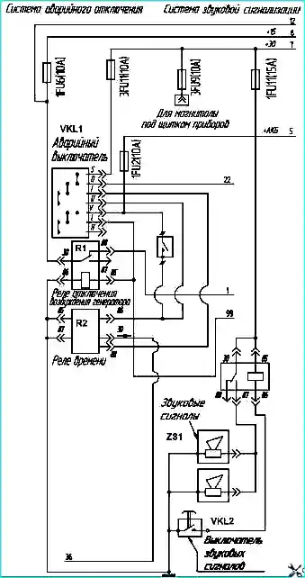
The emergency switch is designed to prevent a fire as a result of a traffic accident.
The emergency switch performs the following functions:
- – disconnecting the storage batteries with a remote switch via relay contacts;
- – turning on all direction indicators in flashing mode via relay contacts and a breaker relay;
- – disconnecting the excitation winding of the generator via relay contacts.
Emergency shutdown is performed by a switch installed on the instrument panel.
The emergency switch can have three key positions:
- - I - off, while the button is not pressed and fixed with a stop flag (driving mode);
- - II - "+ АКБ" shutdown mode and emergency signaling activation, for this purpose, turn the locking flag and press the button to the fixed position;
- - III - battery shutdown, is performed by pressing the switch key to the extreme (non-fixed) position. After stopping pressing, the key returns to the "II" position.
Attention! It is prohibited to hold the emergency switch button in the extreme (non-fixed) position for more than two seconds
Emergency door control system
When the passenger door is opened in an emergency (emergency) manner, a buzzer is activated and rings until the driver closes the door.
When the passenger presses the "Stop on Demand" button, an intermittent ((4-5) sound pulses) buzzer signal is generated and the control lamp lights up in a flashing mode until the bus stops and the door opens for the passenger to disembark.
When the emergency door is opened (single-door bus modification), a continuous buzzer signal is generated and the second indicator lamp with the "Door" symbol until the emergency door is closed and the latch returns to its original position.
Windscreen wipers
The electric windscreen wiper is driven by a DC motor.
The electric motor is switched on by a switch that provides two rotation speeds of the electric motor anchor.
A thermal bimetallic vibration fuse is included in the electric motor circuit, mounted on the windscreen wiper gearbox housing.
A limit switch is provided to set the windscreen wiper blade to the extreme position when it is switched on.
Rotation from the electric motor shaft to the brush drive shaft is transmitted via a worm gear.
For proper operation of the windscreen wiper, it is necessary to prevent prolonged operation of the brushes on dry glass to avoid overheating of the electric motor and scratches on the glass, and also to prevent gasoline or oil from getting on the glass on the rubber bands of the brushes to prevent them from warping.
Blower fan
If the electric motor collector is oily or burnt, wipe it with a rag soaked in gasoline.
If this does not help, clean the collector with glass sandpaper. Then blow with compressed air.
Check the brush pressure, which should be (2-4) N.
Fuses
All bus current consumer circuits are protected by fuses.
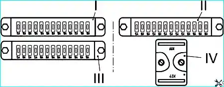
The bus uses 5 fuse blocks: 1 block of "power" fuses BPR-5-4, located in the battery box on the right side, 3 blocks BPR13 and 1 block BPR2.02, located near the steering column.
The layout of the fuse blocks near the steering column is shown in Fig. 2.
Attention! It is prohibited to replace faulty fuses with fuses with a higher rating.
Designations used:
- "+15" – circuit after turning the ignition key to position "I";
- "+30" - circuit after turning on the remote battery switch;
- "+50" - circuit after turning the ignition key to position "II";
- "+АБ" – circuit after turning off the remote battery switch.
Fuse assignment
No. Circuit Fuse rating, A - Fuse assignment
1FU1
- 1FU2 +АБ 10 - Control of passenger compartment doors from the driver's seat; Electronic speedometer
- 1FU3 +AKB 10 - Turn signal relay; Hazard warning lights
- 1FU4 +15 10 - Air dryer; Electronic speedometer
- 1FU5 +15 10 - Shut-off solenoid valve
- 1FU6 +15 10 - Generator excitation relay winding; Generator control lamp; Instrument cluster and tachometer; ABS brakes
- 1FU7 +15 10 - Control lamps; Reversing lights; Glow plug unit control
- 1FU8 +30(40) 10 - Liquid heater control
- 1FU9 +30(40) 10 - Circulation pump
- 1FU10 +30(40) 10 - Windscreen washer; Voltage indicator
- 1FU11 +30(40) 15 - Horns
- 1FU12 +58 10 - Right side lights; Door lights
- 1FU13 +58 10 - Left side lights; Instrument lighting
2FU1
- 2FU2 +30(40) 10 - Right-hand interior lighting
- 2FU3 +30(40) 10 - Left windscreen wiper
- 2FU4 +30(40) 15 - Right windscreen wiper; Brake lights
- 2FU5 +30(40) 10 - Side window blower motor
- 2FU6 +30(60) 15 - Windscreen blower motor
- 2FU7 +30(60) 15 - Driver's seat heater motor; Additional circulation pump (for PAZ-32053-07)
- 2FU8 +30(60) 15 - Left-hand heater motor No. 1; Left-hand heater motor No. 2
- 2FU9 +30(60) 15 - Rear fog lights; Right-hand heater motor No. 1; Right-hand heater motor No. 2
- 2FU10 +56 10 - Left high-beam headlight
- 2FU11 +56 10 - Right high-beam headlight; Indicator lamp "High beam"
- 2FU12 +56 10 - Left headlamp low beam
- 2FU13 +56 10 - Right headlamp low beam
3FU1
- 3FU2 +15 10 - Speed limiting device (for PAZ-32053-77)
- 3FU3 +30(40) 15 - Headlamp power supply
- 3FU4 +30(40) 15 - Left-hand side interior lamps. Portable lamp socket. Engine compartment light
- 3FU5 +30(40) 10 - Forced ventilation electric motors
- 3FU6 +30(40) 10 - Driver's fan electric motor
- 3FU7 +30(40) 10 - Fog lights
- 3FU8 +30(40) 10 - Rear view mirror heating
- 3FU9 +30(40) 10 - Power supply for vehicle talking device; Power supply for radio
- 3FU10 +30(40) 10 - Reserve
- 3FU11 +30(40) 10 - Door drive. Emergency door opening
- 3FU12 +30(40) 10 - Reserve
- 3FU13 +30(40) 10 - Reserve
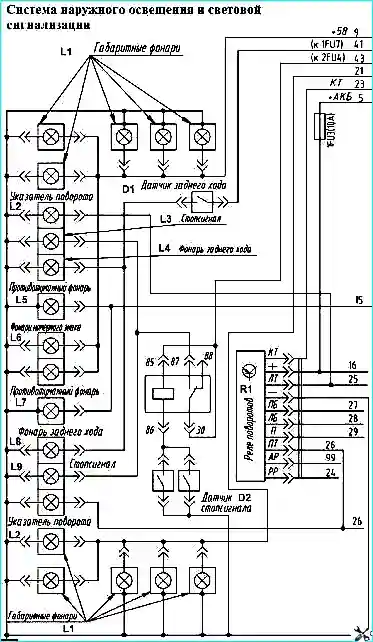
Schematic diagrams of connection of lighting devices and light signaling
")

")
")
")
")
")
")
")