Draining sludge from the fuel coarse filter
Sludge is drained from the fuel coarse filter daily. To drain the sludge you need:
- Stop the engine.
- Turn the lid tap and drain the water from the filter until clean fuel appears.
Attention! Do not overtighten the valve to avoid damaging the threads.
If more than 50 grams of fuel goes down the drain, you need to fill the filter with fuel by bleeding the fuel system to avoid difficulties when starting the engine.
Replacing the fuel coarse filter
- Clean the fuel filter interface area from dirt.
- Unscrew the filter using a special wrench or other available means.
- Wipe the filter mating surface.
- Remove the O-ring.
- Fill the new filter with clean fuel and install it complete with a gasket, which you first lubricate with clean engine oil.
- After the gasket touches the filter housing cup, tighten the filter another 3/4 turn.
Installation of the filter should be done only by hand.
Attention! Do not over-tighten the filter to avoid stripping the thread, damaging the sealing gasket and filter housing.
Replacing the fine fuel filter
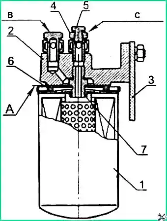
1 — Mann & Hummel WDK962 filter; 2 — filter housing; 3 — bracket; 4 — fitting; 5 — plug (for air release); 6 — gasket; 7 — fitting
Replacement interval: The service life of the fine fuel filter depends on the purity of the fuel used. Replace the filter every 25,000 km or according to the results of diagnostics of the Common Rail system.
Replacement procedure:
- Unscrew filter 1 from fitting 7 in housing 2.
- Install a new Mann & Hummel WDK962, supplied assembled with gasket 6, which is pre-lubricated with engine oil.
- After gasket 6 touches installation pad "A" on body 2, tighten the filter another 3/4 turn. Tighten the filter only by hand.
- Fill the system with fuel.
Filling the fuel system
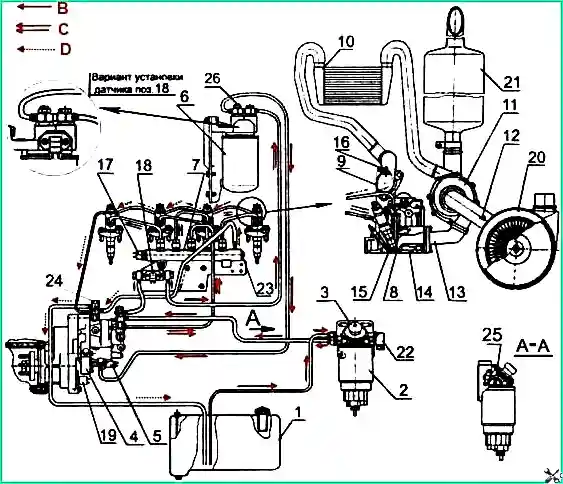
1 — fuel tank; 2 — fuel coarse filter; 3 — manual fuel priming pump; 4 — high pressure fuel pump;
5 — electromagnetic pressure regulator; 6 — fine fuel filter; 7 — high pressure fuel accumulator; 8 — injector;
9 — intake manifold; 10 — charge air cooler; 11 — turbocharger; 12 — air filter clogging sensor;
13 — exhaust manifold; 14 — cylinder head; 15 — glow plug; 16 — charge air temperature and pressure sensor;
17 — high fuel pressure sensor; 18 — fuel temperature and pressure sensor; 19 — camshaft speed sensor;
20 — air cleaner; 21 — muffler; 22 — fuel heater; 23 — pressure limitation valve; 24 — angle rotating bolt;
25 — air release plug; 26 — plug; B — low pressure fuel lines; C — high pressure fuel lines;
D — fuel lines for discharging excess fuel into the tank
Attention! Cranking the diesel engine with the starter when the fuel system is not filled with fuel is prohibited. The high pressure fuel pump will fail.
Bleeding the fuel system (air removal):
- Unscrew plug 26 (Fig. 2), located on the bolt securing the outlet fitting of the fine fuel filter, by 2–3 turns.
- Bleed the system using priming pump 3 located on the coarse fuel filter housing 2.
- Tighten plug 26 (tightening torque 7–8 N·m) when fuel appears without air bubbles.
- Unscrew the angle rotating bolt 24 securing the drainage pipes on the high-pressure pump body by 2–3 turns and continue pumping until fuel appears without air bubbles.
- Tighten bolt 24 (tightening torque 3–4 N·m).
Air cleaner maintenance
Maintenance interval: Service the air cleaner with paper filter elements every 80,000 km (TO-2) or, if necessary, according to the clogging indicator.
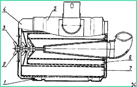
1 — sealing ring; 2 — wing nut; 3 — washer; 4 — cover; 5 — body; 6 — control filter element; 7 — main filter element
Maintenance procedure:
- Remove cover 4.
- Remove main filter element 7.
- Blow off the main filter element with compressed air, first from the inside and then from the outside until the dust is completely removed.
- Clean the supply pipe, the internal surfaces of the housing and the cover from dust and dirt.
- Before assembly, check the condition of the sealing rings.
- When assembling, make sure the filter elements are installed correctly and securely tighten the wing nut by hand.
Important!
- Removing the control filter element 6 from the housing is not recommended.
- Contamination of the control filter element indicates damage to the main filter element (paper curtain rupture, bottom peeling). In this case, blow out the control element and replace the main one.
- To avoid paper curtain rupture, air pressure should be no more than 0.2–0.3 MPa. Direct the air stream at an angle to the filter element surface.
- Do not blow the filter element with exhaust gases or wash it in diesel fuel.
Checking the tightness of the air cleaner and intake tract connections
Inspection interval: Check the tightness of the air cleaner and intake tract connections every 500,000 km (4TO-1).
To check tightness, use the KI-4870 GOSNITI device. If the device is unavailable, check the tightness visually.
Connection requirements:
- Check the condition and fastening of hoses; tighten clamps if necessary.
- Hoses must be placed on fittings for at least 30 mm.
- Cracks and ruptures of hoses are not allowed.
Common Rail fuel system maintenance
Important! Common Rail fuel system maintenance should be carried out at specialized service centers or with the involvement of specialists trained for Common Rail system service.
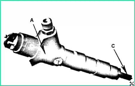
A — injector marking location; B — sprayer marking location
Injector and sprayer replacement:
- Replace injectors based on test results, taking into account the markings of the injector and sprayer.
- Replacing the sprayer in the injector without special equipment and specially trained personnel, as well as during the warranty period, is prohibited.
- During the warranty period, sprayer replacement may only be performed by service centers or workshops specially authorized by Bosch.
Turbocharger maintenance
Maintenance features: The turbocharger does not require special maintenance during operation; its disassembly and repair are not allowed. Partial or complete disassembly, as well as repairs, are possible only after turbocharger removal and only at a specialized facility.
Conditions for reliable turbocharger operation:
- Compliance with the rules and frequency of diesel lubrication and air cleaning system maintenance;
- Using the oil type recommended by the manufacturer;
- Monitoring oil pressure in the lubrication system;
- Timely replacement and cleaning of oil and air filters.
Important! Damaged oil supply and drain lines, as well as air lines connecting to the turbocharger, must be replaced immediately.
When replacing the turbocharger, fill the oil supply hole with clean engine oil up to the flange level. When installing gaskets under pipeline flanges, do not use sealants.
If a malfunction occurs, the compressor should be sent to a workshop where qualified specialists will determine and eliminate the cause.