Setting the fuel injection advance angle for diesel D-245.7E3 / D-245.9E3 bus PAZ 32053-07
The need to install (reinstall) the pulse wheels of the crankshaft and the fuel injection pump drive gearbox shaft to synchronize them may be caused by rearranging the fuel injection pump drive gearbox during routine diesel repairs.
Purpose of the procedure: The installation of pulse wheels according to the proposed scheme is carried out to synchronize the signals from the crankshaft speed sensors and the input shaft of the injection pump drive and is ensured by binding the sensor signals to the common reference point of the shaft position at the moment the piston of the first cylinder passes the top dead center (TDC).
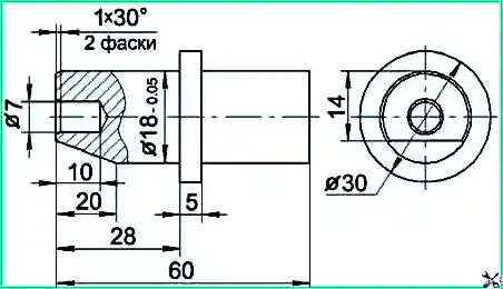
To ensure correct installation of the impulse wheels, it is necessary to make a device for fixing the locating pin in accordance with the sketch (Fig. 1).
Procedure for performing the work
1. Preparation for TDC installation
- Remove the cylinder head cover.
- Install the piston of the first cylinder to the TDC position, turning the crankshaft clockwise using bolt 4 (Fig. 2), until the axis of the 16th tooth of the "crown" of the impulse wheel (when counting counterclockwise from the gap segment at the "crown" of the impulse wheel) coincides with sensor axis 1.

Checking valve condition: Make sure that the intake and exhaust valves of cylinder 1 are closed. If the exhaust valve is open, turn the crankshaft a full turn and recheck the condition of the valves.
2. Setting the piston on the compression stroke (~60° before TDC)
- Turn the crankshaft clockwise using bolt 4 (Fig. 3) approximately two turns.
- On the second turn, remove the lock from the threaded hole of the rear sheet, insert it with the reverse side into the same hole until it stops into the flywheel (for ZIL diesel engines, press the spring-loaded lock until it stops into the flywheel).
- Turn the crankshaft until the lock coincides with the hole in the flywheel.
Control position: In this case, pulse wheel 2 (Fig. 3), mounted on the crankshaft pulley 3, will be positioned in such a way that the axis of sensor 1 will pass along the axis of the sixth tooth of the "crown" of the pulse wheel (when counting counterclockwise from the gap segment at the "crown" of the pulse wheel).
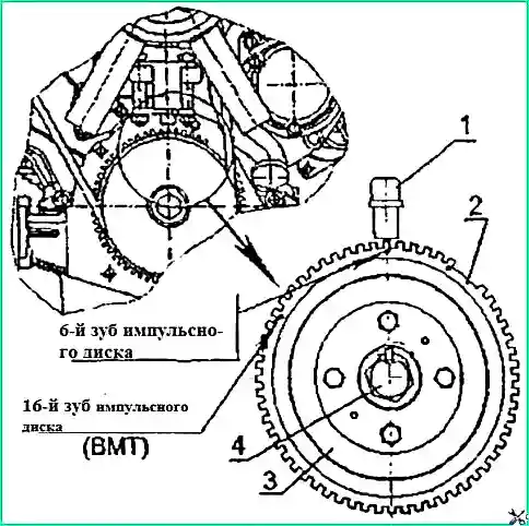
1 — speed sensor; 2 — impulse wheel; 3 — crankshaft pulley; 4 — pulley mounting bolt
Adjusting the sensor position: If there is misalignment between the sensor and the sixth tooth, it is necessary to loosen the fastening of the sensor and ensure that the axes of the sensor and the tooth coincide, then secure the sensor.
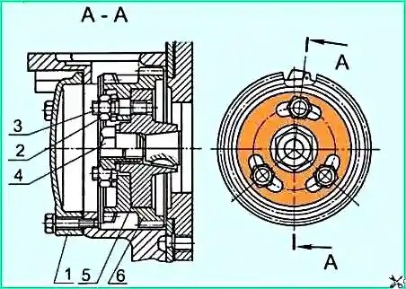
3. Installing the fuel injection pump drive gearbox
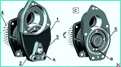
1 — injection pump drive gearbox; 2 — sensor mounting flange; 3 — flange mounting bolt; 4 — gear drive of the gearbox;
5 — gear with impulse pins; A — window for installing the gearbox shaft speed sensor; B — locating pin;
C — gearbox cover removed
Positioning the impulse pins:
- With the gearbox removed, turn clockwise the drive coupling half 5 (Fig. 5) to achieve the position in the window for installing the sensor of two sequentially located pulse pins.
- By slightly turning the drive in the opposite direction, position the locating pin (the first one in the direction of shaft rotation) in the center of the window.
- Install a device into the window to fix the position of the locating pin 1 (Fig. 5) and secure the device with the mounting flange 2 and bolts 3.
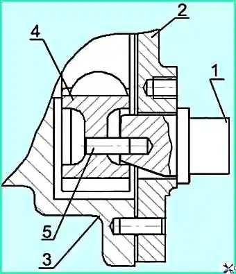
1 — device for fixing the locating pin; 2 — gearbox cover; 3 — gearbox housing; 4 — gear; 5 — locating pin
4. Installing the gearbox on the engine
- Remove the hatch cover 1 (Fig. 6).
- Supporting the drive gear 6 through the hatch window, insert the drive coupling half 5 into the grooves of the drive gear studs 3, thus installing the gearbox.
- Attach the gearbox to the distribution panel.
- Install and tighten nuts 2 to a torque of 35–50 N·m.
1 — hatch cover; 2 — nut and washer; 3 — stud; 4 — special nut; 5 — drive coupling half; 6 — drive gear
5. Final operations
- Remove the mounting flange and remove the mounting fixture.
- Replace the mounting flange and secure it.
- Install the hatch cover, speed sensor and secure them.
- Remove the flywheel retainer and screw its threaded part into the rear sheet.
- Install the cylinder head cover.
Control parameters:
- First cylinder piston at TDC position — axis of the 16th tooth of the impulse wheel coincides with the sensor axis.
- Position ~60° before TDC — sensor axis passes along the axis of the 6th tooth of the impulse wheel.
- Torque for tightening gearbox mounting nuts — 35–50 N·m.
Note: After completing all operations, it is necessary to check the synchronization of the sensor signals and, if necessary, perform adaptation using diagnostic equipment.
")

")
")
")
")
")
")
")