Engine Lubrication System – General Overview
Combined diesel lubrication system. Oil pump - gear type, single-section.
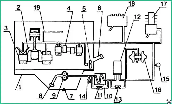
1 — oil sump; 2 — piston cooling nozzles; 3 — crankshaft; 4 — camshaft; 5 — intermediate gear; 6 — oil filler neck; 7 — oil sump plug;
8 — oil receiver; 9 — oil pump; 10 — liquid-oil heat exchanger (LOHE); 11 — bypass valve; 12 — oil filter; 13 — bypass valve;
14 — safety valve; 15 — pressure sensor; 16 — turbocharger; 17 — compressor; 18 — high pressure fuel pump; 19 — oil channel of the rocker arm shaft
Oil pump drive is driven by a gear mounted on the crankshaft.
Oil flow path: The oil pump 9, through the oil receiver 8, takes oil from the oil sump 1 and supplies it through channels in the cylinder block and the oil filter housing channels to the liquid-oil heat exchanger 10, and then to the full-flow oil filter 12 and to the diesel engine oil gallery.
Lubrication of main components:
- From the main gallery, oil flows through channels to all crankshaft main bearings and camshaft journals.
- From the main bearings, oil flows through channels in the crankshaft to all connecting rod bearings.
- From the first main bearing, oil flows to the bushings of the intermediate gear, the fuel pump drive gear, and to the fuel pump.
- Valve mechanism parts are lubricated with oil supplied from the rear camshaft bearing through channels in the block, cylinder head, and into the internal cavity of the rocker arm shaft.
- Oil is supplied to the compressor from the main gallery through drillings in the cylinder block and a special oil line. Oil is drained from the compressor into the diesel crankcase.
- Oil is supplied to the turbocharger bearing assembly through a tube connected at the outlet of the oil filter housing. Oil is drained from the bearing assembly into the oil sump.
Bypass (reducing) valves:
- Installed in the liquid-oil heat exchanger housing — 11 (operating pressure 0.15–0.20 MPa) and in the oil filter — 13 (operating pressure 0.13–0.17 MPa).
- Bypass valves are non-adjustable.
Adjustable safety valve 14, built into the filter housing, is designed to maintain oil pressure in the main oil gallery at 0.25–0.35 MPa. Excess oil is drained through the valve into the diesel crankcase.
Attention! When the diesel engine is running, it is strictly forbidden to unscrew the pressure reducing valve plug!
Lubrication System Maintenance
Maintenance consists of:
- daily monitoring of the oil level in the engine crankcase;
- monitoring oil pressure;
- timely oil and filter changes.
Oil Level Check
Oil level check is performed daily before starting the engine and no earlier than 3 minutes after stopping the engine. The bus must be on a level horizontal surface. The oil level must be between the lower and upper marks on the oil dipstick.
It is prohibited to operate the engine with the oil level below the lower or above the upper mark on the dipstick.
Oil Pressure Monitoring
Oil pressure is monitored by the gauge on the instrument panel:
- When the diesel engine operates at rated speed and coolant temperature 85–95°C — oil pressure must be 0.25–0.35 MPa.
- Oil pressure on a cold engine may reach up to 0.8 MPa.
- At minimum idle speed of a warm engine — oil pressure must be not less than 0.08 MPa.
Oil Change
Oil change interval: every 8,000 km. Oil change is allowed after 10,000 km.
Attention! When using backup oils (M-10 G2K and M-8 G2K) or fuel with high sulfur content, oil change must be performed every 4,000–5,000 km.
Oil change procedure:
- Oil change is performed on a preheated engine.
- To drain the oil, unscrew the oil sump plug.
- After the oil has completely drained, screw the plug back in place.
- Fill oil through the oil filler neck to the upper mark on the dipstick.
Important! Only fill the oil sump with oil recommended by this manual and appropriate for the operating period. Using oils of other brands may cause diesel malfunctions.
Oil Filter Replacement
Oil filter replacement is performed simultaneously with the oil change in the engine crankcase and based on the diagnostic results of the "COMMON RAIL" system.
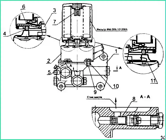
1 — filter housing; 2 — liquid-oil heat exchanger (LOHE); 3 — fitting; 4 — filter gasket; 5 — LOHE gasket;
6 — anti-drain valve; 7 — bypass valve; 8 — safety valve; 9 — coolant drain plug; 10 — sealing ring; 11 — LOHE safety valve
Oil filter replacement procedure:
- Clean the interface between the oil filter and valve housing 1 from dirt.
- Unscrew filter FM 009-1012005 or M5101 from fitting 3, using a special wrench.
- Wipe the mating surface on the valve housing.
- Fill the new filter with clean oil and install (screw onto the fitting) the filter assembly with gasket 4, which must first be lubricated with engine oil.
- After the gasket touches the filter housing cup, tighten the filter another 1–1.5 turns.
Important! The filter should be installed only by hand.
Permissible filter replacements: Instead of filters FM 009-1012005 and M5101, non-separable type filter cartridges may be installed:
- mod. X149 from AC Lelko (France);
- mod. L37198 from Purolator (Italy);
- other brands that have anti-drain and bypass valves in their design with the following dimensions: diameter — 95–105 mm, height — 140–160 mm, thread — 3/4-16UNF.
Safety (Relief) Valve Adjustment
Adjustment is performed when oil pressure in the engine lubrication system drops below 2.5 kgf/cm² on a stopped and warmed-up engine.
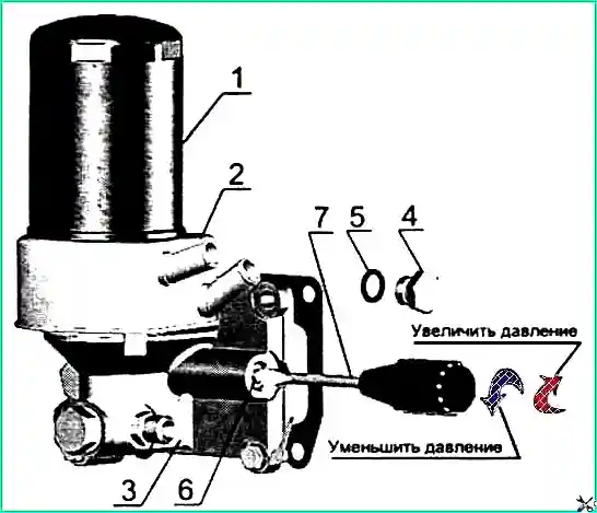
1 — oil filter; 2 — liquid-oil heat exchanger; 3 — oil filter housing; 4 — pressure reducing valve plug;
5 — plug gasket; 6 — adjusting plug; 7 — screwdriver
Adjustment procedure:
- Unscrew plug 4 (Fig. 3), remove gasket 5.
- In the channel of the oil filter housing 3, use screwdriver 7 to turn adjusting plug 6 one turn in the direction of increasing or decreasing pressure (depending on the actual pressure).
- Install gasket 5 and tighten plug 4.
- If necessary, repeat the above steps.
")

")
")
")
")
")
")
")