Anti-lock braking system (ABS) is designed to prevent wheel locking during braking. ABS includes:
- a) wheel speed sensors and pulse rings, speed sensors are installed in the front axle knuckles and in the rear axle flanges. Pulse rings are pressed onto the hubs.
- b) electronic control unit (ECU). The ECU monitors the signals from the speed sensors and controls the corresponding valves (modulators).
The ECU is located on the driver's workstation partition.
- c) pressure control valves (modulators). Modulators are installed near the brake chambers.
- Depending on the incoming signal, the modulator regulates the air pressure in the brake chamber, preventing wheel locking.
- d) signal lamp on the instrument panel. The lamp is designed to warn about the serviceability (malfunction) of the ABS and to read diagnostic codes.
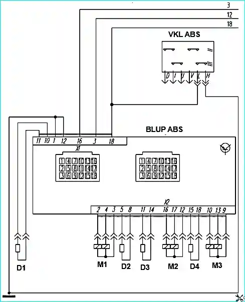
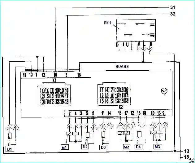
Diagram of the ABS brake system of the PAZ-4234, PAZ-32053-07 bus: VKL ABS - ABS switch; BLUP ABS - ABS control unit; D1 - rear right sensor; D2 - front left sensor; D3 - front right sensor; D4 - rear left sensor; M1 - front axle modulator; M2 - rear left modulator; M3 - rear right modulator
ABS is activated every time there is a possibility of wheel locking.
ABS braking begins when the bus speed exceeds 6 km/h and is accompanied by slight pulsation and characteristic noise of ABS modulators.
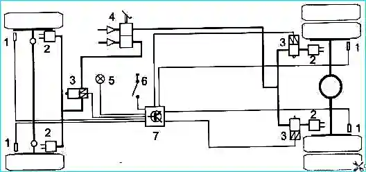
The ABS parts layout diagram is shown in the figure.
For normal ABS operation, the maximum lateral runout of the pulse ring fixed to the wheel hub should not exceed 0.2 mm.
A greater runout may cause the control unit to shut down. The teeth of the pulse ring must not be damaged.
The ECU must be well grounded.
To avoid malfunctions, special care must be taken when applying ground cables.
ABS sensors, modulators, and the ECU itself cannot be repaired if they are faulty and must be replaced only with serviceable ones of the same type.
Otherwise, the proper operation of the ABS system is not guaranteed.
A complete diagnosis of the ABS system must be carried out only with a special diagnostic device.
Carrying out ABS diagnostics
The system diagnostics are performed automatically every time the ignition is turned on.
If the automatic ABS check was successfully completed, the signal lamp goes out 2 seconds after the ignition is turned on, which indicates that the ABS is working properly.
The lamp may remain on continuously after erasing errors and if there are sensor errors in the ECU memory, but at a bus speed of more than 6 km / h, the lamp should go out if the system in good working order.
If a malfunction occurs, the diagnostic indicator lamp lights up and the malfunction is stored in the ECU and coded as a block of light signals.
To determine the malfunction, you need to press the diagnostic button no earlier than 1 second after turning on the ignition and release it. After which the hazard warning light will start flashing.
The first block of flashes of the light indicates the component number, and the second - the error number.
The error codes are given in the table of decoding of light codes.
If the light does not light up immediately after turning on the ignition, this indicates that the incandescent light bulb is faulty and needs to be replaced.
- The duration of the signal light pulse is 0.5 sec.
- The interval between the signal light pulses is 0.5 sec.
- The interval between the first and second block of fault codes is 1.5 sec.
- The interval between the codes malfunctions - 4.5 sec.
Knorr-Bremse ABS light code table.*
Light code - Description - Remedy:
Component No. - Error No.
- 1 – 1 - No malfunction
Left steering axle speed sensor
- 2 – 1 - Air gap too large - Install sensor according to instructions
- 2 – 2 - No sensor signal when braking - Install sensor correctly. Replace the sensor
- 2 – 3 - Bad pulse ring, ABS service life - Replace worn parts
- 2 – 4 - Signal instability - Install the sensor according to the instructions
- 2 – 5 - Loss of sensor signal - Install the sensor according to the instructions. Replace the sensor
- 2 – 6 - Short circuit to GND or battery, or wire break. - Replace the wires
Right steering axle speed sensor
- 3 – 1 - Air gap too large - Install the sensor according to the instructions
- 3 – 2 - No sensor signal when braking - Install the sensor according to the instructions. Replace the sensor
- 3 – 3 - Bad pulse ring, ABS service life - Replace worn parts
- 3 – 5 - Loss of sensor signal - Install the sensor according to the instructions. Replace the sensor
- 3 – 6 - Short circuit to GND or battery, or wire break - Replace the wires
Left steering axle speed sensor
- 2 – 1 - Air gap too large - Install the sensor according to the instructions
- 2 – 2 - No signal when braking - Install the sensor according to the instructions. Replace the sensor
- 2 – 3 - Bad pulse ring, ABS service life - Replace worn parts
- 2 – 4 - Signal instability - Install the sensor according to the instructions. Replace worn parts
- 2 – 5 - Loss of sensor signal - Install the sensor correctly. Replace the sensor.
Right steering axle speed sensor
- 3 – 1 - Air gap too large - Install the sensor correctly
- 3 – 2 - No sensor signal when braking - Install the sensor correctly. Replace the sensor
- 3 – 3 - Bad pulse ring, ABS service life - Replace worn parts
- 3 – 4 - Signal instability - Install the sensor correctly. Replace worn parts.
- 3 – 5 - Loss of sensor signal - Install the sensor correctly. Replace the sensor
- 3 – 6 - Short circuit GND or battery, or broken wire - Replace the wires
Left axle speed sensor
- 4 – 1 - Air gap too large - Install the sensor correctly
- 4 – 2 - No sensor signal when braking - Install the sensor correctly. Replace the sensor
- 4 – 3 - Bad pulse ring, ABS service life - Replace worn parts
- 4 – 4 - Signal instability - a) Install the sensor according to the instructions; b) Replace worn parts
- 4 – 5 - Loss of sensor signal - a) Install the sensor according to the instructions; b) Replace the sensor
- 4 – 6 - Short circuit to GND or battery, or broken wire - Replace the wires
Right drive axle speed sensor
- 5 – 1 - Air gap too large - a) Install the sensor according to the instructions; b) Replace worn parts
- 5 – 2 - No sensor signal when braking - a) Install the sensor according to the instructions; b) Replace the sensor
- 5 – 3 - Bad pulse ring, ABS service life - Replace worn parts
- 5 – 4 - Signal instability - a) Install the sensor according to the instructions; b) Replace worn parts
- 5 – 5 - Loss of sensor signal - a) Install the sensor according to the instructions; b) Replace the sensor
- 5 – 6 - Short to GND or battery, or open wire - Replace wires
Left steering axis modulator
- 8 – 1 - Short circuit of the reset coil to battery - Replace the modulator
- 8 – 2 - Short circuit of the reset coil to GND - Replace the modulator
- 8 – 3 - Open wire of the reset coil - Replace the modulator
- 8 – 4 - Open wire on the common pin - Replace the modulator
- 8 – 5 - Short circuit of the lift coil to battery - Replace the modulator
- 8 – 6 - Short circuit of the lift coil to GND - Replace modulator
- 11 – 1 - Short circuit of reset coil to battery - Replace modulator
- 11 – 2 - Short circuit of reset coil to GND - Replace modulator
- 11 – 3 - Open circuit of reset coil wire - Replace modulator
- 11 – 4 - Open circuit of wire on common pin - Replace modulator
- 11 – 5 - Short circuit of lift coil to battery - Replace modulator
- 11 – 6 - Short circuit of lift coil to lift GND - Replace modulator
- 11 – 7 - Broken lift coil wire - Replace modulator
- 11 – 8 - Valve configuration error - Check the location of the wires in the modulator connector and install them in accordance with the diagram. Ground connection pins of diagonals
- 10 – 10 - Diagonal 1 is shorted to battery - Check wiring and replace faulty
- 10 – 11 - Diagonal 1 is shorted to GND - Check wiring and replace faulty
- 10 – 12 - All modulators are shorted to GND - Check wiring and replace faulty
Internal ECU malfunctions
- 15 – From 1 to 11 - ECU defective - Replace unit
Power supply
- 16 – 1 - diagonal 1, high voltage - Check generator operation, troubleshoot
- 16 – 2 - diagonal 1, low voltage - Check generator operation, troubleshoot
- 16 – 3 - diagonal 1, broken wire - Check wiring and replace faulty
- 16 – 4 - GND_PCV1 broken wire or large voltage difference to GND_ECU - Check wiring and replace faulty
- 16 – 9 - U_ECU high voltage - a) Check generator operation, troubleshoot; b) Check wiring and replace faulty
- 16 – 10 - U_ECU low voltage (or U_ECU high) - a) Check generator operation, troubleshoot; b) Check the wiring and replace the faulty one
Special errors
- 17 – 5 - Large difference between the sizes of the front and rear tires - Replace the tires
- 17 – 10 - Defective hazard warning lamp - Replace the lamp
- 17 – 12 - Problem with the memory of sensor parameters - a) Install the sensor in accordance with the instructions; b) Replace the sensor; c) with the ABS system turned on, conduct a test drive of the bus (acceleration-braking) at a bus speed of 6 to 10 km/h.
- 17 – 13 - Axle 1 or 2 sensors are mixed up - Install the sensors in accordance with the ABS diagram
*- to start diagnostics of the Knorr-Bremse ABS, turn on the ignition and press the diagnostic button for 0.5-8 seconds.
After releasing the button, the lamp lights up for 0.5 sec and goes out. Then after 1 second the codes light up.
You can stop the error codes by pressing the diagnostic button again.
WABCO* ABS light code table
Name
Light code – Description
- Troubleshooting:
- 1 – 1 - No fault
ABS magnetic valve
- 2 – 1 - Front right
- 2 – 2 - Front left
- 2 – 3 - Rear right
- 2 – 4 - Rear left
- Check the magnetic valve cable. There is a permanent or intermittent break in the wires to the intake or exhaust valves or in the "common" wire, or a short to "minus".
Sensor: increased air gap
- 3 – 1 - Front right
- 3 – 2 - Front left
- 3 – 3 - Rear right
- 3 – 4 - Rear left
- Check the runout of the wheel bearing. Move the sensor to the rotor. Check the sensor cable and connectors for intermittent contact
Sensor: Short Circuit/Broken Wire
- 4 – 1 - Front Right
- 4 – 2 - Front Left
- 4 – 3 - Rear Right
- 4 – 4 - Rear Left
- Check the sensor cable. Open or short to negative or positive or between the sensor wires
Lost Signal/Tire Size
- 5 – 1 - Front Right
- 5 – 2 - Front Left
- 5 – 3 - Rear Right
- Check the sensor cable for intermittent contact. Check the rotor for damage. Connect another sensor to check.
Rotor
- 6 – 1 - Front right
- 6 – 2 - Front left
- 6 – 3 - Rear right
- 6 – 4 - Rear left
- Check the rotor for damage. Replace the Rotor
System functions
- 7 – 4 - ABS lamp
- Check the cable and the warning lamp. Was the diagnostic button pressed for more than 16 seconds?
Electronic unit
- 8 – 1 - Low supply voltage - Check the power cable and fuse
- 8 – 2 - High supply voltage - Check the battery and generator
- 8 – 3 - Internal error - Replace the ABS unit if the error persists
- 8 – 4 - Configuration error - Incorrect electronic unit / parameterization
- 8 – 5 - Connection to the negative terminal of the battery - Check the ground on the electronic unit and magnetic valves
“- to start the WABCO ABS diagnostics, turn on the ignition and press the diagnostic button for 0.5-3 seconds.
After releasing the button, the lamp lights up for 0.5 seconds and goes out.
Then after 1.5 sec. the codes light up.
The interval between two blocks of signals of one malfunction is 1.5 sec.
The interval between signals of two malfunctions is 4 sec. To turn off diagnostics, turn off the ignition.
Erasing the error memory
After troubleshooting the system, it is necessary to erase the error from the error memory of the control unit. To do this, you must:
- for Knorr-Bremse - with the ignition off, press the diagnostic key and release it only after the ignition is on.
In less than 3 seconds, the error memory is erased;
- for WABCO - with the ignition on, press the diagnostic key for 3-6 seconds and release it.
After 1.5 seconds, eight quick flashes of the lamp indicate that the errors have been erased from the ECU memory.
After 4 seconds, three flashes of the lamp indicate the correct ABS configuration. Then turn off the ignition.
Final ABS check
During the final check, check and do the following:
- 1. Check the correctness of the ABS configuration. To do this, press the diagnostic button twice with a break of less than 1 second. After that, the signal lamp should flash in two blocks: 1-1 (i.e. -12 V) and 2-3 (i.e. - 4S / 3K with one modulator on the front axle).
- 2. Erase the error memory.
- 3. Count the light codes.
- 4. The hazard warning lamp should go out after turning on the ignition after 2 seconds.
- 5. Conduct a dynamic test. It is necessary to conduct bus runs (acceleration - braking) on a level surface. The hazard warning light should go out when the bus reaches a speed of 6 - 10 km/h.
If the ABS is faulty, the braking system remains operational, but it is important to remember that the bus's controllability may be impaired due to wheel locking.
If controllability is significantly impaired, the ABS must be checked immediately in a suitable workshop to eliminate the fault and return the system to normal operation.
Caution! When welding on the bus, disconnect all electrical connectors from the ECU.
")

")
")
")
")
")
")
")