The table shows the probable causes of brake system failure, as well as methods for eliminating failures
Probable cause (Method of elimination)
Air cylinders are not filled (the pressure regulator is activated):
- Clogged pipeline from the compressor to the pressure regulator
Clean the pipeline
- Damage to the pressure regulator valve
Replace the pressure regulator valve
Air cylinders are not filled to the lower pressure (the pressure regulator does not work):
- Leakage of compressed air from the pneumatic drive
Depending on the location of the leak: replace the pipeline, hose, or tighten the fittings of pipelines and hoses, or tighten the fasteners of the connecting elements, or replace the faulty device
- Compressor faulty
Repair or replace the compressor
The air tank of the rear brake circuit is not filled:
- The section of the four-circuit safety valve connected to the rear brake cylinder does not work or is not adjusted
Adjust or replace the device
The air tank of the front brake circuit is not filled:
- The section of the four-circuit safety valve connected to the front brake cylinder does not work or is not adjusted
Adjust or replace the device
The air cylinder of the parking brake system is not filled:
- The section of the 4-circuit safety valve connected to the parking brake system cylinder is not working or is not adjusted
Adjust or replace the device
Frequent operation of the pressure regulator:
- Leakage of compressed air from the pneumatic drive in the area from the regulator to the safety valve
Depending on the location of the leak: replace the pipeline, hose, or tighten the fittings of pipelines and hoses, or tighten the fasteners of the connecting elements, or replace the faulty device
Air tanks are filling slowly:
- Leakage of compressed air from the pneumatic drive due to leakage: at the junction of pipelines; damage to pipelines; at the joints of device body parts due to their damage; malfunction of the atmospheric terminals of the devices.
Depending on the location of the leak: replace the pipeline, hose, or tighten the fittings of pipelines and hoses, or tighten the fasteners of the connecting elements, or replace the faulty device
- The compressor is faulty due to wear or damage to parts
Repair or replace the compressor
The pressure in the air cylinders is above or below normal (the pressure regulator is activated):
- The pressure regulator is out of adjustment or the pressure gauge is faulty
Adjust the pressure regulator. Replace the pressure gauge.
Ineffective braking when pressing the brake pedal:
- Leakage of compressed air from the pneumatic drive
Depending on the location of the leak: replace the pipeline, hose, or tighten the fittings of pipelines and hoses, or tighten the fasteners of the connecting elements, or replace the faulty device
- Oiling the pad linings
Wash the linings with kerosene, replace the hub cuffs
- Large gap between the pads and the brake drum in one or more brake mechanisms
Check the strokes of the rods in all brake mechanisms and, if necessary, replace the adjusting lever
- The adjustment of the brake valve drive is broken
Adjust the brake valve drive
- Brake valve is faulty
Repair or replace the brake valve
- The working brake mechanisms are misaligned or faulty
Adjust or repair brake mechanisms
- Leakage of the brake chamber membrane
Replace the membrane
- Limitation of pedal travel due to contamination of the cavity under the rubber cover of the brake valve lever
Restore the stroke of the tap pusher; if necessary, replace the rubber boot
- The stroke of the brake chamber rods exceeds the set value
Adjust the stroke of the rods
When the parking brake valve is turned on, the rear wheels do not brake:
- Leakage of compressed air from the pneumatic drive in the drive circuit of the parking brake system
Depending on the location of the leak: replace the pipeline, hose, or tighten the fittings of pipelines and hoses, or tighten the fasteners of the connecting elements, or replace the faulty device
- The stroke of the rear wheel brake chambers is greater than normal
Adjust the stroke of the rods
- The brake chamber with spring energy accumulator is faulty
Replace the faulty device
- The brake valve of the parking brake system is faulty
Replace the faulty device
- Accelerator valve is faulty
Replace the faulty device
- Four-circuit safety valve is faulty
Replace faulty apparatus
The brake lights do not light up or go out when you press the pedal or apply the parking brake:
- The brake light sensors are faulty or the wiring is faulty
Replace the faulty sensor or repair the electrical wiring
- One of the pneumatic drive devices is faulty
Replace the faulty device
The wheels do not release the brakes after releasing the brake pedal when the parking brake is off:
- Adjustment lever failure
Replace lever
- The two-section brake valve is faulty or its drive is out of alignment
Adjust the tap drive or replace the tap
- The parking brake valve is faulty
Replace the faulty device
- Accelerator valve is faulty
Replace the faulty device
- The seal between the cavity of the spring energy accumulator and the working chamber is broken
Replace the brake chamber with spring energy accumulator
The rear wheels do not release when the parking brake is released:
- Leakage of compressed air from the pneumatic drive in the drive circuit of the parking brake system
Depending on the location of the leak: replace the pipeline, hose, or tighten the fittings of pipelines and hoses, or tighten the fasteners of the connecting elements, or replace the faulty device
One of the wheels does not release:
- Broken tension springs
Replace springs
- Jamming of the expansion fist shaft
Wash and lubricate the shaft with bushings
Presence of oil in the first air cylinder:
- Increased oil release from the compressor, which caused a failure of the dryer adsorbent element
Repair or replace the compressor. Replace the desiccant element
Presence of condensation in air cylinders:
- The dryer filter is clogged, the check valve of the regeneration cylinder is stuck, or the purge hole in it is clogged
Carry out maintenance of the dryer
Possible malfunctions of the pneumatic devices of the brake system
Compressor
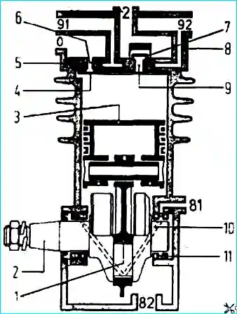
The compressor does not develop the required pressure:
- Compressed air leaks in the pneumatic system
Check the condition of pipelines, pneumatic devices and their connections
- The head is loose
Tighten the head fastening nuts
- The gasket between the head and the valve plate is damaged
Replace gasket
- Coking of compressor valves
Clean the valves and valve plate from carbon deposits
- Wear of piston rings
Replace the rings and check the serviceability of the air filter
Noise when the compressor is running:
- Increasing the gaps between the connecting rod and the crankshaft journal
Replace connecting rods
- The response pressure of the membrane chamber is very high
Membrane defect 16. Replace membrane
- The chamber rod does not return to its original position after releasing air
Defective return spring 19. Replace the spring
- Actuation pressure of the spring energy accumulator
The working surface of cylinder 7 is damaged
- Seal 6 is swollen
Replace defective parts
When air is supplied, the spring energy accumulator does not decelerate:
- Seal 6 or ring 3 is leaking
Replace the O-ring and seal
- Compressed air passes through the connector of cylinder 7 and flange 14
Defective rubber sealing ring in the connector. Replace ring
The spring energy accumulator does not work efficiently:
- Spring defect 8
Replace the spring
High response pressure of the spring energy accumulator:
- The working surface of the cylinder is damaged
Replace cylinder
The energy accumulator spring does not compress when air is supplied to the cylinder. There is air outlet from the drainage holes of the brake chamber housing and from the opening of the chamber itself:
- The piston sealing ring is damaged
Replace ring
Brake valve
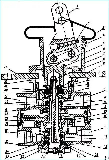
When valve lever 1 is free, air leaks into the atmosphere through outlet window 21.
Defects in valves 17, 29 and springs 13, 24.
Replace defective parts and clean valve seats
Air leakage at housing connector:
- O-ring defect
Replace ring
- Damage to the end surfaces of the housings.
Clean up the damaged area
As the pressure in the upper section increases, the pressure in the lower section slowly increases:
- Swelling of O-rings
Replace defective rings
Crane lever jammed:
- Contamination of the lever mechanism due to damage to the protective cover
Clean the parts of the lever mechanism from dirt, replace the defective cover
Violation of the following action along the lever:
- Defect of elastic element 31
Replace the elastic element
Parking brake valve
Air leakage into the atmosphere:
- Defect of the valve or its spring
Replace valve or spring
Violation of the following action of the crane:
- Breakage of the balancing spring. Swelling of the O-ring
Check and replace the spring or O-ring
Quick release valve
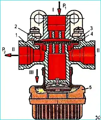
Leakage of compressed air at the connector of the cover and housing:
- Defective sealing ring 4
Replace ring
- Cover 2 is loose
Tighten the screws
When compressed air is supplied to the outlet / air is released into the atmosphere:
- Aperture defect 3
Replace the diaphragm
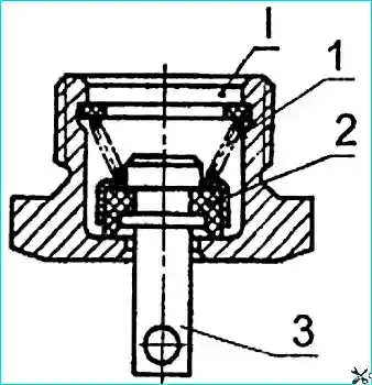
Test outlet valve

Valve leakage:
- Seal defect on pusher 5
Replace the seal
- Defect in the sealing gasket between fitting 1 and body 2
Replace gasket
Condensate drain valve
Tap leakage:
- Valve 2 or housing is dirty or defective
Operate the crane. Clean the valve or body
Air leak from under the valve body gasket
- Defects (nicks, burrs, etc.) on the sealing gasket, the ends of the valve or the receiver boss
Replace the gasket or condensate drain valve. Clean the end of the receiver boss
")

")
")
")
")
")
")
")