Suspension System
The front and rear suspensions of the bus (Fig. 1 and Fig. 2) consist of longitudinal semi-elliptical springs and hydraulic shock absorbers.
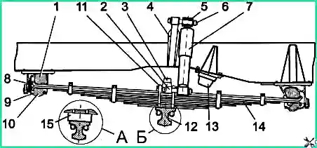
1 — upper spring cup support; 2 — shock absorber bracket; 3 — main buffer; 4 — shock absorber bracket; 5 — bushing; 6 — shock absorber pin;
7 — shock absorber; 8 — stop; 9 — bracket cover; 10 — lower support; 11 — spring stepladder; 12 — front axle beam; 13 — buffer;
14 — spring; 15 — spacer; A — for KAAZ OJSC axle; B — for Ryazan Avtoagregat LLC axle
The rear suspension also includes additional (correction) springs.
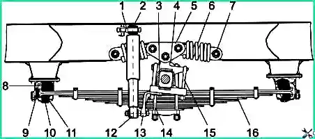
1 — shock absorber pin; 2 — shock absorber bushing; 3 — rear axle housing; 4 — buffer; 5 — shackle; 6 — spring; 7 — spring pin;
8 — upper support; 9 — stop; 10 — lower support; 11 — bracket cover; 12 — shock absorber; 13 — shock absorber bracket; 14 — spring stepladder;
15 — spring ladder; 16 — spring
On the PAZ-4234 bus, a body anti-roll bar is installed in the front suspension (Fig. 3).
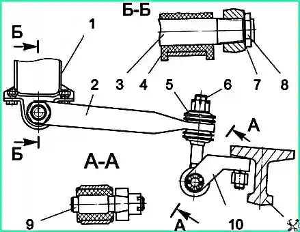
1 — torsion bar support; 2 — stabilizer lever; 3 — stabilizer torsion bar; 4 — torsion bar cushion; 5 — stabilizer strut cushion;
6 — stabilizer strut; 7 — adjusting washer; 8 — torsion bar nut; 9 — stabilizer pin; 10 — strut bracket; 11 — front axle beam
All springs are attached to the base of the body using rubber pads (supports). The pads are clamped in the brackets with covers along with the spring cups. Thrust rubber pads are installed in the front brackets of the front and rear springs to prevent longitudinal movement of the springs forward. The necessary longitudinal movements during deflections occur due to the displacement of the rear ends of the springs. Spring deflections are limited by rubber buffers.
Telescopic shock absorbers are designed to dampen vibrations that occur when the bus moves on an uneven road. Prolonged rocking of the bus after moving over an uneven road indicates a malfunction of the shock absorbers. In this case, it is necessary to identify the faulty shock absorber and replace it or repair it.
To check the performance of the shock absorber, you need to hold it vertically by the lower eye and pump it by the upper eye at least 5 times. For a working shock absorber, the rod should move evenly, without jerking or vibration, when a constant load of 220 N is applied. The movement time over the length of the extension stroke (100 mm) should be no more than 10 seconds. If the shock absorber pumps without resistance or the resistance is very high, it should be repaired or replaced.
In addition to loss of efficiency, the shock absorber may leak oil through the rod seal in the upper part.
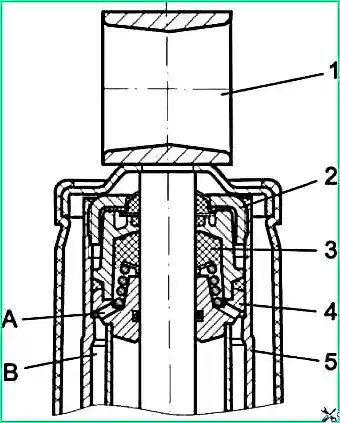
1 — eye; 2 — reservoir nut; 3 — rod seal; 4 — rod guide; 5 — reservoir body;
A — hole for draining liquid into the reservoir; B — reservoir cavity
In this case, tighten the reservoir nut 2 (Fig. 4). To do this, you need to remove the shock absorber from the bus. If after tightening the nut the fluid leak is not eliminated, you need to replace the rod seal 3. When installing the oil seal, its large outer diameter should face down, towards the working cylinder. Only in this position is the normal operation of the oil deflector grooves of the oil seal ensured.
Only shock absorber fluid can be filled into the shock absorber according to the lubrication chart. When pouring fluid into the shock absorber, it is necessary to have operating conditions that ensure special cleanliness. Clogged shock absorber valve systems lead to its malfunction.
During suspension maintenance, check the integrity of the spring leaves, the tightening of the nuts of the spring stepladders and additional springs, the fastening of the nuts of the spring support covers, the condition of the spring support pads, shock absorber bushings, additional spring bushings, anti-roll bar cushions, the fastening of the pin nuts, torsion bar and stabilizer bracket mounting. The stabilizer torsion bar nut 7 (Fig. 3) is locked by punching in the place opposite the groove in the torsion bar.
Failures of springs can be: breakage of individual springs, breakage or weakening of the end cups of the main leaves and spring clamps, a decrease in the deflection of the spring in the free state, and corrosion of the leaves. Corrosion of leaves can significantly reduce their durability. Therefore, during repair work, it is recommended to clean the leaves and lubricate the rubbing surfaces of the springs with graphite lubricant. When disassembling and assembling springs, it is not recommended to hit the surface of the leaves with a hammer, as this can lead to their subsequent breakage during operation.
The durability and reliability of the rubber cushions of the spring supports depends on their correct installation. When installing cushions, their distortions are not allowed. Incorrectly placed cushions do not self-align when the caps are tightened, which leads to their rapid wear. To properly fasten the ends of the spring in the rubber pads, the spring must be straightened using a special device.
Front Axle
The bus can be equipped with a front axle manufactured by KAAZ OJSC or Ryazan-Avtoagregat LLC.
Front Axle "KAAZ"
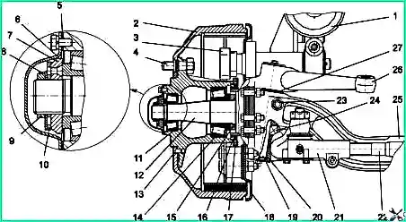
1 — wheel rim; 2 — brake drum; 3 — expansion cam; 4 — wheel mounting stud; 5 — gasket; 6 — hub cap; 7 — nut; 8 — lock washer;
9 — lock nut; 10 — lock ring; 11 — outer hub bearing; 12 — steering knuckle axle; 13 — drum mounting screw; 14 — inner hub bearing;
15 — bearing thrust ring; 16 — oil seal; 17 — ABS pulse ring; 18 — brake shield; 19 — kingpin; 20 — kingpin bushing; 21 — tie rod end;
22 — steering tie rod; 23 — wedge pin; 24 — support bearing; 25 — front axle beam; 26 — steering knuckle arm; 27 — adjusting washer
The front axle of KAAZ OJSC (Fig. 5) consists of an I-section beam, steering knuckles, and kingpins secured in the beam bosses with wedges. Between the end of the upper eye of the fork and the end of the beam boss, adjusting washers are installed, with the help of which the gap in the connection is eliminated. The kingpins have two flats under the wedge, located at an angle of 90°, which allows you to rotate the kingpin when worn on one side. The supporting surfaces of the kingpin and the thrust bearing must be lubricated through two grease nipples.
The wheel hubs rotate on two tapered roller bearings. The bearings are protected from contamination by hub caps with gaskets and a double-edged collar mounted on a ring behind the inner hub bearing.
Front Axle "RAA"
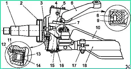
1 — steering knuckle axle; 2 — hub cuff ring; 3 — stop; 4 — kingpin grease nipple; 5 — upper kingpin cover; 6 — upper lever; 7 — kingpin wedge;
8 — kingpin bushing cuff; 9 — cuff clamp; 10 — front axle beam; 11 — support bearing ring; 12 — support bearing cuff; 13 — support bearing;
14 — support bearing seal; 15 — kingpin; 16 — kingpin bushing; 17 — tie rod end clamp; 18 — steering tie rod
In the design of the axle of Ryazan-Avtoagregat LLC, rubber seals are provided to retain the lubricant of the kingpin assembly. When installing the upper seal, make sure that its edge is directed towards the end of the beam. When replacing kingpins and bushings, you must ensure that the rings are installed correctly in the grooves of the steering knuckles, so as not to cut off the rings with the kingpins. If the ring does not hold well in the groove, it must be lubricated with grease. The supporting surfaces of the kingpin and the thrust bearing must be lubricated through two grease nipples. To control the release of lubricant, a bleed valve is installed in the upper cover of the kingpin.
A description of the steering linkage parts is presented in the article "Features and malfunctions of the steering control of the PAZ-32053-07, PAZ-4234 bus".
When servicing the front axle, the condition of the beam is checked, the gaps in the kingpin joint are checked, the kingpins and wheel hub bearings are lubricated, and the toe-in and steering angle of the wheels are adjusted. Adjustment of the hub bearings is carried out when the clearances increase or if the hub heats up due to excessive tightening of the bearing nut.
Adjusting the Front Wheel Hub Bearings (KAAZ Axle)
- Raise the wheel with a jack so that the tires do not touch the support.
- Remove the hub cap 6 (Fig. 5) and bend the lock washer 8 from the edge of the lock nut 9.
- Unscrew the lock nut 9, remove the lock washer and lock ring 10.
- Rotating the hub in both directions so that the rollers are correctly installed on the conical surfaces of the rings, tighten the nut-washer 7 until the hub begins to brake.
- Place the lock ring on and loosen the nut-washer approximately 1/8 turn until the pin on the nut-washer aligns with the nearest hole in the lock ring.
- Rotate the wheel with a strong push of your hand. The wheel should rotate freely and have no noticeable play.
- Put on the lock washer, tighten the lock nut to a torque of 14–16 kgf·m and bend the lock washer.
After adjustment, the wheel should rotate evenly and freely in both directions. The gap should not exceed 0.15 mm.
Adjusting the Front Wheel Hub Bearings (RAA Axle)
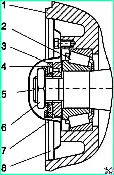
1 — hub; 2 — outer hub bearing; 3 — lock ring; 4 — lock washer; 5 — knuckle axle; 6 — lock nut; 7 — adjusting nut; 8 — hub cap
- Raise the front axle or wheel with a jack.
- Make sure that when the wheel rotates, the brake shoes do not touch the drum.
- Remove the hub cap 8 (Fig. 7) and, bending the lock washer 4, unscrew the lock nut 6 with a wrench (Fig. 8).
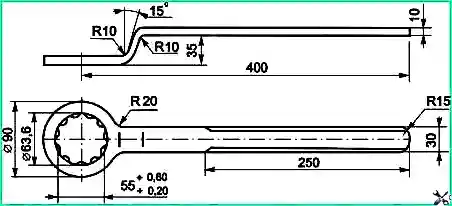
- Turn the wheel in both directions and tighten the nut with a wrench (Fig. 9). Tightening torque (65-80) N·m. After tightening, the hub should not rotate. Axial play is not allowed.
- Unscrew the adjusting nut (1/4-1/3) turn until the nut pin aligns with the nearest hole in the lock ring.
- Install the lock washer, tighten the lock nut with a tightening torque of (250-300) kgf·cm, and bend the lock washer onto one of the faces of the nut.
After adjustment, the wheel should rotate evenly and freely in both directions. The gap should not exceed 0.25 mm.
Adjusting Wheel Toe-In
- Place the bus on a horizontal platform. Set the front wheels to a straight-ahead position. Check the tire pressure and, if necessary, adjust it to normal.
- Between the inner edges of the wheel tires, at a diameter of (730-740) mm, in front of the front axle, insert a sliding ruler parallel to the platform at the height of the wheel axle axis.
- Take a measurement, noting where the ruler will be installed.
- Roll the bus forward 1/2 turn of the wheel and, placing a ruler at the marks behind the front axle, take a measurement. If the difference in measurements does not fall within the limits of (2-4) mm, then you need to make an adjustment.
- Loosen the coupling bolts of both ends of the transverse link and, by rotating it with a pipe wrench, achieve the required amount of wheel toe-in. After adjustment, secure the tie rod end bolts.
Changing the length of the transverse steering rod occurs due to:
- different thread pitches at the ends of the rod (on the left — 1.5 mm, on the right — 2 mm) at the front axle manufactured by KAAZ;
- different thread directions at the ends of the rods at the front axle manufactured by "RAA".
If to establish the toe-in of the wheels of the KAAZ axle, a change in the length of the rod by more than 5 mm is required, then remove the transverse rod from the bus and set the required length by moving the left and right tips the same way. Then perform the final adjustment as described above.
Adjustment of wheel angles is recommended to be carried out simultaneously with wheel toe-in adjustment. Adjustment is carried out using thrust bolts screwed into the flanges of the kingpins. The thrust bolts must first be screwed in to the limit, and then unscrewed until the required angle is obtained and secured with a lock nut. The angle of rotation of the right wheel to the right (left to the left) is (37±1)°.
In the extreme positions of the wheels, there should be no gap between the adjusting bolt and the front axle beam. In addition, when turning right while driving, the left wheel should not touch the longitudinal steering rod.
The angles of inclination of the kingpins and camber of the wheels, which change due to wear and deformation of parts during the operation of the bus, are not adjustable. In case of increased wear of the front wheel tires, it is necessary to check the wheel camber, the longitudinal and lateral inclination of the kingpins, as well as the wheel turning angles. Checking angles is performed using special equipment. Angle values are listed in the appendix to this manual.
When operating a bus, it is necessary to especially carefully monitor the timely lubrication and condition of the front axle kingpin assembly. It is necessary to replace worn parts in a timely manner, since excessive clearance (play) in the kingpin joint creates the possibility of an impact load, which can lead to premature destruction of the hub bearings, enlargement of the beam holes for the kingpins, and breakage of the steering axle.
The wear of the kingpin and bushings is determined by rocking the wheel. To do this, you need to jack up the front axle and, holding the wheel tire from above and below, rock the wheel. You should first check that the wheel bearings are adjusted correctly.
Checking the radial clearance in the kingpin joint is carried out using a dial indicator. The kingpin connection is in good condition if the radial clearance in the connection does not exceed 0.75 mm. If the movement of the upper outer edge of the brake shield in the vertical plane is less than 2 mm, then you can turn the kingpin around its axis 1/4 turn to the second flat under the locking pin. If the indicated movement is more than 2 mm, then the worn kingpin and bushings should be replaced.
Checking the axial clearance is carried out without hanging the wheel. The feeler gauge is inserted between the beam boss and the steering knuckle eye. If the axial clearance exceeds 0.25 mm (0.75 mm for the front axle "RAA"), then it is necessary to adjust the clearance by selecting the thickness of the shims or replacing the thrust bearing of the kingpin.