Generator
An alternating current generator with a built-in semiconductor rectifier and an integrated voltage regulator is the main source of electrical energy
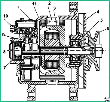
The generator is a three-phase twelve-pole synchronous electric machine with a built-in rectifier unit, an interference suppression capacitor, a brush holder with a voltage regulator and a draft ventilation system.
The generator operates in a single-wire circuit of the bus electrical equipment with the "minus" connected to the body.
The generator is connected in parallel with the batteries and provides power to consumers in any engine operating mode, as well as recharging the batteries.
The generator is installed on the engine and is driven by the engine crankshaft pulley.
The generator is attached to the engine with two paws through a bracket and with a third paw to the tension bar, when moving along which the generator drive belt is tensioned.
The schematic diagram of the generator is shown in Fig. 2
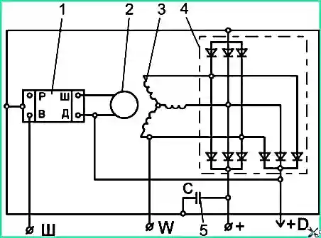
Terminals: "+" - for connection to the battery and load; "Ш" - for connection to the ignition switch and battery charge indicator lamp;
"W" - for connection to the tachometer; "+0" - for connection to the starter interlock circuit
Attention! Disconnect and connect the wires to the generator only with the battery disconnected.
Proper operation of the generator is ensured only if all contacts are securely electrically connected, including between the generator housing and the engine.
Operation of the generator with the battery disconnected can damage the voltage regulator, as well as other consumers of the on-board network.
Maintenance and repair of the generator should be carried out only in specialized workshops by qualified specialists.
Check the rectifier unit only on a disassembled generator with a disconnected stator winding.
Check only from a DC source with a voltage of no more than 24 V, connected in series with a test lamp.
Generator maintenance
To ensure generator operation, it is recommended to keep the generator clean and follow the following maintenance rules.
Check the generator's performance daily using the readings of the control lamp and voltmeter located in the instrument cluster on the instrument panel.
When the engine is started, the control lamp should light up and go out after the engine is started.
When the generator is operating normally, the voltmeter needle is in the green zone of the "G" scale (generator).
If the voltmeter needle is in any of the red zones of this scale, the generator is faulty.
Check the condition and tension of the drive belts daily. During TO-1, checks are carried out using measuring instruments.
Particular attention should be paid to belt tension at the beginning of their operation for (1-2) days.
The belt tension is adjusted so that when pressing on the middle of the belt with a force of 40 N, the deflection is within (10-15) mm.
When installing new belts, it is permissible to set a smaller deflection value - 10 mm.
The belt tension is adjusted using a tension bar.
To do this, after loosening the generator fastening to the bracket and bar, move the generator body to the required position and secure it.
Attention! If the belt tension is weak, the generator will not give full power. If the belt is over-tensioned or skewed, the alternator will fail prematurely.
The criterion for the limit state of the belt is delamination of more than 1/3 of the length, the presence of rubber cracks down to the cord cord and the impossibility of compensating for elongation in the drive.
When checking the tension and installing a new belt, check for damage, oiliness of the pulley groove surfaces and the location of the pulley grooves in the same plane.
At least once a month, it is recommended to check the charge level of the batteries, which should be at least 75%.
During TO-2 without removing the alternator from the engine, check the fastening of the alternator to the engine and the fastening of the nuts of the tie bolts of the covers.
Check the tightness and cleanliness of all places where the wires are connected to the generator and batteries. If necessary, clean the connection points, tighten the contact nuts and screws.
During each seasonal maintenance (without removing the generator), check the condition of the brush assembly in the following order:
Disconnect the wire from the "Ш" terminal of the generator.
Unscrew the screws securing the brush holder and carefully remove it.
Check free movement (without jamming or jerking) of the brushes in the guides of the brush holder.
Check the height of the brushes, which should be at least 8 mm. If necessary, replace the brushes.
Install the brush holder with brushes on the generator in the reverse order.
The generator should be removed from the engine only for routine repairs and work related to wear of the slip rings, replacement of bearings and other special work.
If the wear of the slip rings exceeds 0.5 mm in diameter, the rings must be turned.
Starter
The starter is a four-pole electric motor with an electromagnetic traction relay and a drive with a freewheel clutch.
The starter is switched on using the instrument and starter switch key.
Attention! It is prohibited to turn on the starter when the engine is running, as well as to move the bus from a place by turning the transmission through the engine with the starter.
Checking the condition of the starter
Every 120,000 km of run:
Check the tightening of the mounting bolts, tighten them if necessary.
Strip the wire tips to the terminals of the starter and battery and tighten their fasteners.
Remove the cover from the collector side and check the condition of the brush-collector unit.
The working surface of the collector must be smooth and not have significant burns.
If the collector is dirty or has traces of significant burns, wipe it with a clean cloth soaked in gasoline.
If it is impossible to remove dirt or burns by wiping, clean the collector with fine sandpaper.
If there is significant burnt-on damage to the collector that cannot be cleaned, grind the collector on a machine.
The brushes must move freely in the brush holders and fit tightly to the collector.
If the brushes are extremely worn, or if there are significant chips, replace them with new ones.
Blow out the brush-collector unit and the cover from the collector side with compressed air.
Check the condition of the starter relay contact system.
If there is significant burnt-on damage, clean the contact bolts and the contact plate with sandpaper or a file, removing the unevenness caused by the burnt-on damage, without disturbing the flatness of the contact surfaces of the copper bolts.
If there is significant wear of the plate and bolts, turn the contact plate over and turn the contact bolts 180°.
Check the ease of movement of the drive along the armature shaft. When switching the relay on and off, the drive must move along the splines of the armature shaft without jamming.
Remove contaminated thickened grease with wear products from the crankcase from the inner surfaces of the drive guide sleeve (splined and smooth) and adjacent parts of the shaft, which significantly impedes the axial movement of the drive along the splines of the shaft when the gear engages with the flywheel ring gear.
Apply a thin layer of CIATIM-221 (CIATIM-201) grease to the cleaned surfaces.
Visually inspect the condition of the drive gear and thrust washers.
Control parameter: The gap between the end of the gear and the thrust washers in the engaged position should be (2-4) mm.
Possible generator and starter malfunctions and troubleshooting methods
Generator malfunctions
The generator does not provide charging current (the control lamp is on, the voltmeter needle is in the left red zone of the "G" scale):
Generator excitation circuit unloading relay faulty - Replace the relay
No reliable contact between the brushes and rings:
- the brushes are stuck in the guides - check the condition of the brush assembly and eliminate the malfunction;
- the brushes are worn out - replace the brushes;
- the rings are dirty or oily - wipe the rings with a clean cloth soaked in gasoline.
- If this method does not remove the dirt, clean the rings with sandpaper with a glass coating and wipe again
Unsoldering of the excitation winding terminals from slip rings or break in excitation coil - Remove the brush holder with voltage regulator.
Check the resistance of the excitation coil between the slip rings. If unsoldered, solder; if broken, replace the rotor.
Fault (breakdown or open circuit) of the rectifier block diodes - Check and, if necessary, replace the rectifier block
Fault (breakdown or open circuit) of the additional rectifier block diodes - Check and, if necessary, replace the rectifier block
Open or short circuit in the stator winding - Disassemble the generator, remove the stator and check the resistance of the phase windings.
If the stator is in good condition, the resistance of the phase windings should not differ from each other by more than 10%.
If there is an open or short circuit, replace the stator.
Open or short circuit of the rectifier block valves - Replace the rectifier block
The charge indicator lamp flashes, the ammeter needle fluctuates
Drive belt is loose - Tighten the belt
No reliable contact between brushes and rings - See above
The voltmeter needle is in the right red zone of the "G" scale
Voltage regulator faulty - Replace the voltage regulator
Short circuit in the generator brush assembly or in the circuit between the generator and the regulator - Eliminate the short circuit
Battery faulty - Check, charge or replace the battery if necessary
Excessive tension or skewing of the drive belt - Adjust the belt tension and eliminate skew
Mechanical faults
Bearing noise
Bearings are worn or damaged - Replace bearings
Starter faults
The starter does not work (the headlights do not dim when turned on)
- Break or faulty wiring - Check wiring to starter and fix fault.
- No contact of brushes with commutator - Wipe the commutator with a cloth soaked in gasoline, or clean the commutator with sandpaper. Check for sticking of brushes in brush holders.
- Broken connections inside starter - Remove the starter, check and eliminate defects or replace the starter
- Solenoid relay faulty - Clean the starter relay contacts or rotate the contact bolts in the sockets by 180°, and install the contact plate with the reverse side, or replace the relay
The starter does not turn the engine or turns it very slowly
- Low engine temperature (in winter) - Warm up the engine
- Use of oil not suitable for the season - Change the oil
- Corrosion of battery contacts - Clean the contact connections
- Discharged or faulty batteries - Charge or replace the batteries
- Poor contact in the starter power supply circuit - Clean and tighten the wire terminals
- Burnt relay contacts - Clean the relay contacts
- Poor contact of brushes with the commutator - Clean the commutator and brushes, eliminate sticking, or replace the brushes
- Weak contact at battery terminals - Clean, secure, lubricate
The starter armature rotates at high speed, but does not turn the engine
- The drive has failed - Replace the drive
- The starter adjustment is disturbed - Adjust the starter
The relay works intermittently (turns the starter on and immediately turns it off)
- The relay holding winding is broken - Replace the relay
- The batteries are discharged - Charge or replace the batteries
The drive gear systematically does not engage with the flywheel ring gear during normal relay operation
- The flywheel ring gear teeth ends are heavily clogged - Replace the flywheel ring gear
- The starter adjustment is disturbed - See above
- Seizure of the gear on the shaft due to lack of or poor quality lubrication - Clean the shaft and splines from dirt and lubricate with CIATIM-221 (-201) grease
- Milling of the drive gear teeth due to its engagement on a running engine - Replace the drive
After starting the engine, the starter remains in the on state
The contact plate is welded to the bolts of the starter contact relay - Clean the starter relay contacts or rotate the contact bolts in the sockets by 180°, and install the contact plate with the opposite side. Or replace the relay
")

")
")
")
")
")
")
")