The crank mechanism consists of: a crankshaft, pistons with piston rings and pins, connecting rods, main and connecting rod bearings, a flywheel
The crankshaft is made of steel, has five main journals and four connecting rod journals.
The crankshaft is sealed with cuffs at the front and rear.
The piston is made of aluminum alloy.
There is a combustion chamber at the bottom of the piston.
The piston has three grooves in the upper part - compression rings are installed in the first two, and an oil scraper ring is installed in the third.
An insert made of special cast iron is poured under the groove of the upper compression ring.
Piston rings
The upper compression ring is made of high-strength cast iron, in cross-section it has the shape of an isosceles trapezoid, the second compression ring is conical.
On the end surface of the lock, the compression rings are marked “Top” (“TOP”). Box type oil scraper ring with spring expander.
The connecting rod is steel. To lubricate the piston pin, there are holes in the upper end of the connecting rod and the bushing.
The distribution mechanism consists of a camshaft, intake and exhaust valves, as well as parts for their installation and drive: pushers, rods, rocker arms, adjusting screws with nuts, plates with crackers, springs, struts and rocker arm axles.
The camshaft is driven by the crankshaft through timing gears
Steel pushers. The camshaft cams are made with a slight inclination, so the tappets rotate during operation.
The rocker arm axis is hollow and has eight radial holes for supplying oil to the rocker arms.
The sealing collars installed on the valve guides prevent oil from entering the diesel cylinders and exhaust manifold through the gaps between the valve stems and the valve guides.
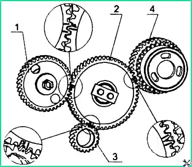
Coordinated operation of the high-pressure fuel pump and the gas distribution mechanism is ensured by installing the timing gears according to the marks in accordance with Figure 1.
Check the tightening of the cylinder head bolts after the end of the run-in and at every second maintenance-2 on a warm engine.
Before checking the tightness of the bolts, it is necessary to remove the cap and cylinder head cover, as well as remove the rocker arm axle with rocker arms and struts.
Then use a torque wrench to check the tightness and tighten if necessary.
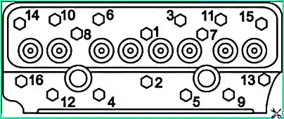
Tighten the cylinder head mounting bolts as shown in Figure 2, in ascending order of numbers, applying torque (210-230) Nm.
After the first tightening, you should re-check the torque on each bolt, observing the specified order.
After checking the tightness of the bolts, reinstall the rocker arm axle and adjust the gap between the valves and rocker arms.
Gas distribution mechanism
Check the gaps between the valves and rocker arms and, if necessary, adjust them at each maintenance-2, as well as after removing the cylinder head, tightening the cylinder head bolts, and when knocking occurs.
The gap between the rocker arm striker and the end of the valve stem when checking on a cold engine (coolant and oil temperature no more than 60 °C) should be:
- - intake valves - (0.15-0.30) mm;
- - exhaust valves – (0.35-0.50) mm.
The gap between the rocker arm striker and the end of the valve stem when checking on a cold engine should be:
- - intake valves - (0.20-0.25) mm;
- - exhaust valves – (0.40-0.45) mm.
Adjustment of valves should be carried out in the following sequence:
Remove the cylinder head cover and check the fastening of the rocker arm axle struts.
Turn the crankshaft by the flywheel crown through the hole in the clutch housing until the valves in the first cylinder overlap (the inlet valve of the 1st cylinder begins to open, and the exhaust valve finishes closing).
Adjust the gaps in the 4th, 6th, 7th and 8th valves (counting from the fan).
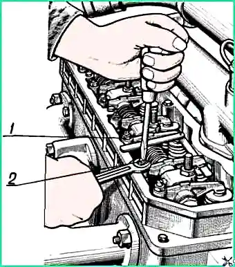
To adjust the rear first loosen lock nut 1 (Fig. 3) of screw 2 on the rocker arm of the adjustable valve and, turning the screw, set the required gap on the feeler gauge between the rocker arm and the valve stem.
Rotate the crankshaft one revolution, setting the overlap in the 4th cylinder, and adjust the clearances in the 1st, 2nd, 3rd and 5th valves.
After adjusting the gaps, tighten the nuts of the adjusting screws to a torque of (40-50) Nm, and the feeler gauge should come out of the gap with a force of (3-5) N.
")

")
")
")
")
")
")
")