Features and maintenance of the D-245.7E2 / D-245.9E2 engine lubrication system
Combined diesel lubrication system
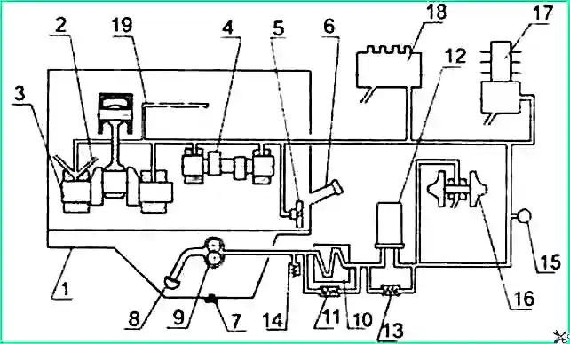
Lubrication system diagram: 1 - oil sump; 2 - piston cooling nozzles; 3 - crankshaft; 4 - camshaft; 5 - intermediate gear; 6 - oil filler neck; 7 - oil sump plug; 8 – oil receiver; 9 - oil pump; 10 - liquid-oil heat exchanger (LHT); 11 - bypass valve; 12 - oil filter; 13 - bypass valve; 14 - safety valve; 15 - pressure sensor; 16 - turbocharger; 17 - compressor; 18 - high pressure fuel pump; 19 - oil channel of the rocker axis
Oil pump - gear type, single-section.
The oil pump is driven by a gear mounted on the crankshaft.
The oil pump 9, through the oil receiver 8, takes oil from the oil sump 1 and supplies it through the channels in the cylinder block and the channels of the oil filter housing to the liquid-oil heat exchanger 10, and then to the full-flow oil filter 12 and to the diesel oil line.
From the main diesel line, oil flows through channels in the cylinder block to all crankshaft main bearings and camshaft journals.
From the main bearings, oil flows through channels in the crankshaft to all connecting rod bearings.
From the first main bearing, oil flows through special channels to the bushings of the intermediate gear and the fuel pump drive gear, as well as to the fuel pump.
Valve mechanism parts are lubricated with oil supplied from the rear camshaft bearing through channels in the block, cylinder head, drilling in the IV rocker arm post into the internal cavity of the rocker arm axis and through a hole in the rocker arm bushing, from which it goes through the channel to the adjusting screw and rod .
Oil is supplied to the compressor from the main line through drillings in the cylinder block and a special oil pipeline.
The oil is drained from the compressor into the diesel crankcase.
Oil is supplied to the bearing assembly of the turbocharger through a tube connected at the outlet of the oil filter housing.
From the bearing assembly of the turbocharger, oil is discharged through a tube into the oil sump
Bypass (reducing) valves are installed in the housing of the liquid-oil heat exchanger - 11 (response pressure value - 0.15-0.20 mPa) and in the oil filter - 13 (response pressure value 0.13-0.17 mPa) .
When starting a diesel engine on cold oil, when the resistance to the passage of oil in the liquid-oil heat exchanger exceeds 0.15-0.2 mPa, the bypass valve opens and the oil, bypassing the liquid-oil heat exchanger, enters the oil filter, and when resistance in the oil filter is 0.13-0.17 mPa, the oil filter bypass valve opens and the oil, bypassing the oil filter, enters the oil line.
Bypass valves are unregulated.
An adjustable safety valve 14 is built into the filter housing, designed to maintain oil pressure in the main oil line at 0.25-0.35 mPa.
Excess oil is drained through the valve into the diesel crankcase.
In case of excessive clogging, when the oil filter resistance becomes higher than 0.13-0.17 mPa, the filter bypass valve also opens, and the oil, bypassing the oil filter, enters the oil line.
Attention! When the diesel engine is running, it is strictly forbidden to unscrew the pressure reducing valve plug!
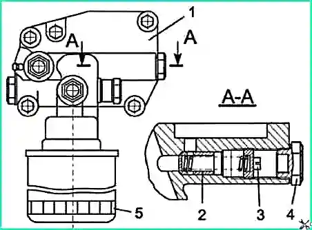
Oil filter: 1- valve body; 2 - safety valve; 3 - adjusting bolt; 4 - valve plug; 5 - valve body
The oil filter (Fig. 2) consists of a housing assembled with valves and a replaceable one-piece filter mod. FM 009-1012005.
The non-separable filter has anti-drainage and bypass valves.
In case of excessive filter clogging or when starting a diesel engine on cold oil, when the filter resistance becomes higher (0.13-0.17) MPa, the bypass valve opens and the oil, bypassing the filter paper, enters the oil line.
The filter housing 1 has an adjustable safety valve 2.
Valve 2 is adjusted to pressure (0.25-0.35) MPa and serves to maintain the required oil pressure in the main diesel line.
When the oil pressure in the engine lubrication system drops below 0.25 MPa (2.5 kgf/cm 2), it is allowed to adjust the safety (drain) valve 2. The adjustment should be carried out with the engine turned off and a warm engine.
To adjust safety valve 2, you need to unscrew the valve plug 4 and turn the adjusting bolt 3.
Tightening the adjusting bolt 3 increases the pressure in the lubrication system.
Maintenance of the lubrication system consists of daily monitoring of the oil level in the engine crankcase, monitoring oil pressure, and timely changing the oil and filter.
Check the oil level daily before starting the engine and no earlier than 3 minutes after stopping the engine. The bus must be installed on a flat, horizontal platform.
The oil level should be between the lower and upper marks of the oil dipstick.
It is prohibited to operate the engine with the oil level below the lower and above the upper mark of the oil gauge.
The oil pressure of the engine lubrication system is controlled by an indicator located on the instrument panel.
When the diesel engine is operating at the rated speed and coolant temperature (85-95) °C, the oil pressure should be at the level of (0.25-0.35) MPa, the pressure value on a cold engine is allowed up to 0.8 MPa .
At minimum idle speed, the oil pressure in the lubrication system of a warm engine must be at least 0.08 MPa.
The oil is changed every 8,000 km. Oil changes are allowed after 10,000 km.
Attention! In the case of using backup oils or fuel with a high sulfur content, the oil should be changed after (4000-5000) km.
Double oils include: M-10 G2K and M-8 G2K.
The oil in the diesel crankcase is changed on a preheated engine.
To drain the oil, you need to unscrew the oil sump plug. After all the oil has flowed out of the crankcase, screw the plug back into place.
Fill diesel oil through the oil filler pipe to the level of the upper mark on the oil gauge.
Only fill the oil sump with oil recommended in this manual and appropriate for the period of operation.
The use of oils of other brands may lead to diesel malfunctions.
Replacing the oil filter is carried out simultaneously with changing the oil in the engine crankcase according to the lubrication chart (via one TO-1) in the following sequence:
- 1) clean the interface between the oil filter and valve body 1 from dirt;
- 2) unscrew filter 2, wipe the mating surface in the valve body, fill the new filter with clean oil and install the filter assembly with the gasket, which is pre-lubricated with engine oil;
- 3) after the gasket touches the housing cup, tighten the filter another 3/4 turn.
Installation of the filter should be done only by hand.
Instead of the FM 009-1012005 filter, it is allowed to install filter cartridges of a non-separable type: mod. X149 from AC Lelko (France), mod. L37198 from Purolator (Italy) and other companies that have anti-drainage and bypass valves in their design with the main dimensions: - diameter - (95-105) mm; - height - (140- 160) mm; - landing thread - 3/4" – 16 UNF.
")

")
")
")
")
")
")
")