Engine Cooling System Overview
Closed-type engine cooling system, with forced circulation of coolant from a centrifugal pump.
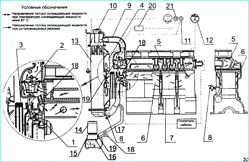
1 — pump; 2 — thermostat; 3 — pump drive belt; 4 — fan; 5 — cylinder head cooling jacket; 6 — cylinder block cooling jacket;
7 — cylinder block liner; 8 — drain taps; 9 — pipe; 10 — filler plug; 11 — emergency temperature indicator; 12 — temperature indicator;
13 — radiator; 14 — oil filter; 15 — liquid-oil heat exchanger; 16 — drain plug; 17 — outlet pipe; 18 — supply pipe;
19 — coolant temperature sensor; 20 — electronic unit of the CRS system; 21 — diagnostic lamp of the CRS system
Temperature control: The temperature of the coolant in the system is controlled using a remote thermometer, the sensor of which is installed in the cylinder head. In addition, a light sensor for emergency coolant temperature is installed in the thermostat housing cover.
Attention! It is prohibited to operate the diesel engine when the warning light for emergency coolant temperature in the cooling system comes on.
Temperature range: The temperature of the coolant in the cooling system must be maintained between 85–95°C.
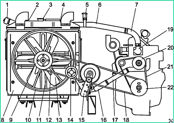
1 — filler plug; 2 — expansion tank; 3 — upper radiator cap; 4 — radiator; 5 — pipe mounting bracket; 6 — radiator supply pipe;
7, 16 — pipe; 8 — fan casing; 9 — fan pulley; 10 — fan drive housing; 11 — fan casing mounting frame; 12 — belt;
13 — fan; 14 — tension roller; 15 — intermediate support bracket; 17 — outlet pipe; 18 — belt; 19 — thermostat housing;
20 — water pump pulley; 21 — belt; 22 — crankshaft pulley
Thermostat: The thermostat with solid filler is designed to accelerate engine warm-up after starting and automatically regulate the temperature at various loads and ambient temperatures. The temperature at which the main valve begins to open is 87 ± 2°C.
Expansion tank: The expansion tank is designed to compensate for changes in the volume of coolant during heating and to remove air.
Unit drive: The water pump and generator are driven from the engine crankshaft pulley using two belts. The cooling system fan is driven from the crankshaft pulley through the intermediate support pulley.
Attention! To avoid scale formation and engine damage, do not use water in the cooling system. If malfunctions associated with a coolant leak occur, short-term use of water is allowed until the malfunction is eliminated.
Cooling System Maintenance
Daily maintenance:
- Check the fluid level in the expansion tank (the level must be above the "MIN" mark).
- Monitor the tightness of connections.
Important! Operation of the bus with an empty expansion tank is not permitted.
Coolant replacement: Once a year in the fall, during maintenance, the coolant should be replaced. Before replacing the fluid, make sure the system is tight.
Attention! Using coolant of insufficient density can cause engine destruction. Monitor the coolant temperature. Normal operating temperature should be 85–95°C.
Actions when temperature rises: If the temperature rises above operating temperature, check:
- the coolant level in the expansion tank (and radiator if necessary);
- the tightness of the radiator and pipelines;
- the tension of the fan belts and their condition.
Flushing the Cooling System
Schedule: If necessary, but at least every 120,000 km of bus operation, flush the cooling system to remove contaminants. For flushing, use a solution of 50–60 grams of soda ash per 1 liter of water.
Flushing procedure:
- Pour 2 liters of kerosene into the radiator and fill the system with the prepared solution.
- Start the diesel engine and run for 8–10 hours or 350–400 km.
- Drain the solution and flush the cooling system with clean water.
Belt Tension Adjustment
Tension control: Tension is checked using a spring dynamometer based on belt deflection or using the KI-8920 device.
Permissible belt deflection under a load of 4 ± 0.2 kgf:
- Between the crankshaft and intermediate support pulleys — 14–20 mm;
- Between the intermediate support and fan shaft pulleys — 13–18 mm;
- Between the crankshaft and generator pulleys — 15–22 mm;
- Between the generator and water pump pulleys — 7–12 mm;
- Between the crankshaft and compressor pulleys — 15–22 mm.
Fan belt tension adjustment: Between the crankshaft pulley and intermediate support is performed by turning the eccentric axis of the intermediate support after loosening the mounting nuts. Belt tension between the fan and intermediate support pulleys is adjusted using the tension roller.
Generator and water pump drive belt tension adjustment: Is performed by turning the generator housing.
Compressor drive belt tension adjustment (D-245.9E3): Is performed using a roller through the tension mechanism. Before tensioning, loosen the tension roller shaft locking bolt and the adjusting screw locking nut, then turn the nut on the adjusting screw to move the screw together with the tension roller.
Important! If one of the belts is worn or damaged, replace them as a complete set (both belts).
Lubrication of Cooling System Components
Water pump lubrication: "Litol-24" lubricant is placed in the bearing cavity of the water pump during assembly and is replaced only after repair (disassembly) of the unit.
The bearings of the water pump, fan shaft, and intermediate fan support do not require lubrication during the entire period of operation.
")

")
")
")
")
")
")
")