Common Rail Fuel System – General Overview
The diesel power system consists of a Common Rail accumulator injection system, low and high pressure fuel lines, intake and exhaust manifolds; turbocharger; fine and coarse fuel filters, air cleaner, fuel tank, charge air cooler.
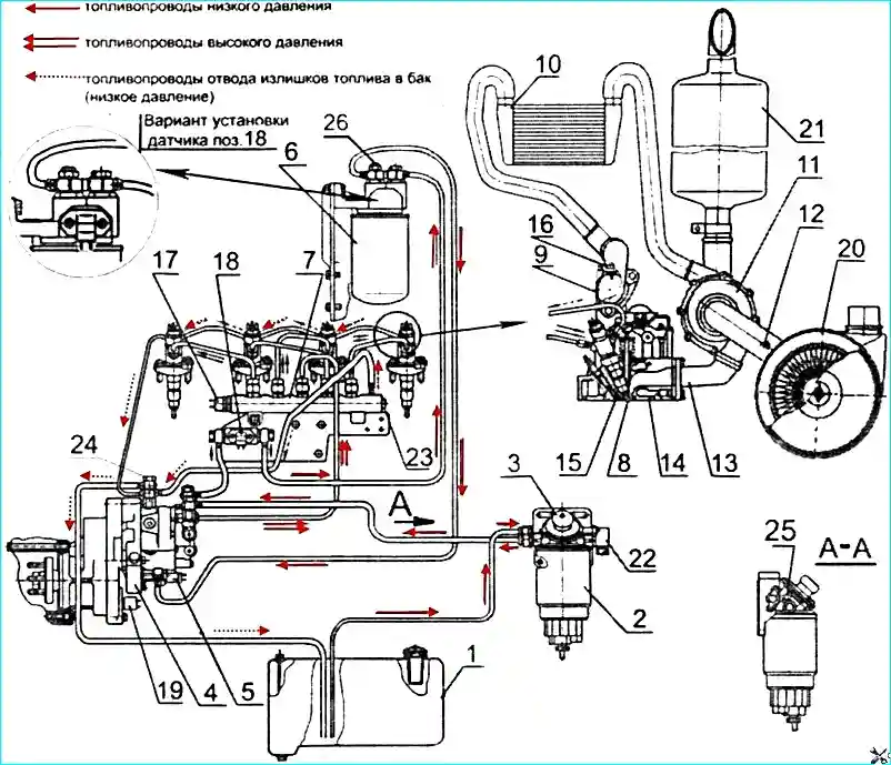
1 — fuel tank; 2 — fuel coarse filter; 3 — manual fuel priming pump; 4 — high pressure fuel pump; 5 — electromagnetic pressure regulator; 6 — fine fuel filter;
7 — high pressure fuel accumulator; 8 — injector; 9 — intake manifold; 10 — charge air cooler; 11 — turbocharger; 12 — air filter clogging sensor;
13 — exhaust manifold; 14 — cylinder head; 15 — glow plug; 16 — charge air temperature and pressure sensor; 17 — high fuel pressure sensor;
18 — fuel temperature and pressure sensor; 19 — camshaft speed sensor; 20 — air cleaner; 21 — muffler; 22 — fuel heater; 23 — pressure limitation valve;
24 — angle rotating bolt; 25 — air release plug; 26 — plug
Common Rail accumulator injection system: consists of a fuel pump, injectors, a high-pressure fuel accumulator, speed sensors (crankshaft and camshaft), sensors for the state of the working environment (pressure and temperature of fuel and air), electromagnetic actuators (fuel pressure regulator, injector solenoid valves), electronic control unit, control and communication circuits, control and diagnostic panel.
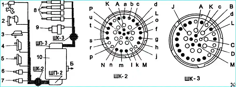
1 — crankshaft speed sensor; 2 — camshaft speed sensor; 3 — fuel temperature and pressure sensor; 4 — oil temperature and pressure sensor;
5 — charge air temperature and pressure sensor; 6 — high fuel pressure sensor; 7 — coolant temperature sensor; 8 — injectors;
9 — pressure regulator; 10 — electronic control unit; B — to the bus on-board network
High Pressure Fuel Pump (HPFP, mod. CP3.3)
Purpose: creating a fuel reserve, maintaining and regulating pressure in the fuel accumulator.
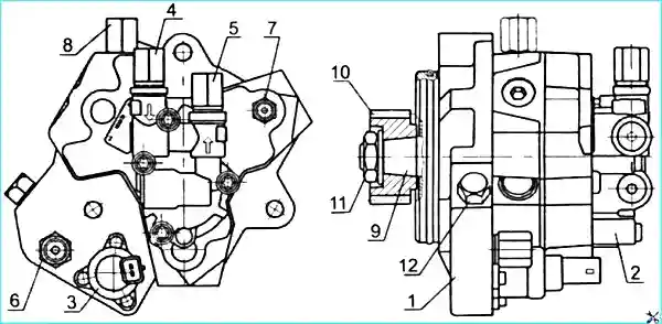
1 — high pressure fuel pump; 2 — fuel priming pump; 3 — electromagnetic pressure regulator; 4 — fuel supply fitting from the coarse filter;
5 — fuel outlet fitting to the fine filter; 6 — fuel supply fitting from the fine filter; 7 — fuel outlet fitting to the accumulator;
8 — fuel outlet fitting to the tank; 9 — drive shaft; 10 — drive gear; 11 — nut; 12 — plug
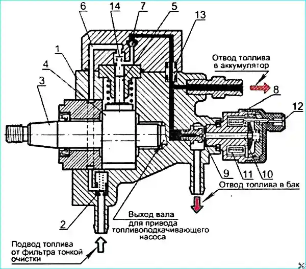
1 — pump housing; 2 — safety valve with throttle hole; 3 — drive shaft; 4 — cam rotor; 5 — plunger; 6 — supply channel;
7 — outlet valve; 8 — pressure control valve; 9 — ball; 10 — armature; 11 — electromagnet; 12 — electromagnet terminals;
13 — seal; 14 — inlet valve
HPFP design: In the pump housing, three plungers 5 are located radially at an angle of 120°, and a cam rotor 4 is installed on the drive shaft 3 (the cams are located at 120° intervals). The pump drive shaft has a gear drive from a gearbox, the input shaft of which, through the drive half-coupling, is kinematically connected to the diesel crankshaft.
HPFP operating principle: Fuel that has passed through the coarse filter is supplied under pressure of 0.8–0.9 MPa by the priming pump through the fine filter to the inlet fitting of the HPFP. Lubrication and cooling of HPFP parts is carried out by diesel fuel.
The advancing cam of the rotor moves the plunger upward, compressing the fuel. When the pressure reaches the level maintained in the accumulator, the outlet valve opens, and compressed fuel enters the high-pressure circuit.
Pressure control valve: Sets the pressure in the accumulator depending on engine load, speed, and thermal condition. If the pressure is too high, the valve opens and some fuel is returned to the fuel tank through the return line.
High Pressure Fuel Accumulator (Rail)
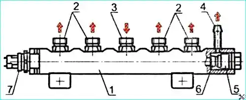
1 — fuel accumulator; 2 — outlet fittings; 3 — supply fitting; 4 — return drain fitting; 5 — pressure limitation valve;
6 — valve core shut-off cone; 7 — fuel pressure sensor
Rail purpose: The high-pressure fuel accumulator (Rail) is a volumetric fuel reservoir. At the same time, it smooths out pressure fluctuations arising from pulsating fuel supply from the HPFP and injector operation.
Accumulator 1 is shaped like a pipe, with a fuel pressure sensor 7 and pressure limitation valve 5 installed at its ends. Fuel from the HPFP is directed through the high-pressure line to the inlet fitting 3 of the rail and then to the injectors.
Pressure limitation valve: Acts as a pressure reducing (safety) valve. When the operating pressure is exceeded, the cone moves away from the seat under pressure, and fuel is discharged into the return line.
Injector
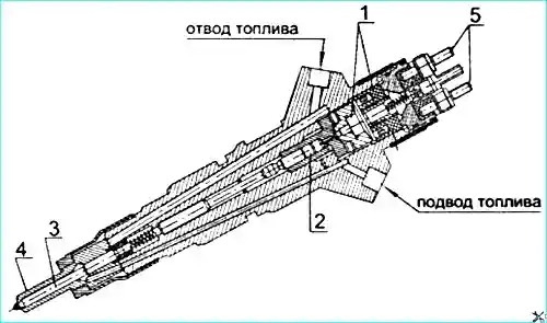
1 — solenoid valve; 2 — control valve; 3 — spray needle; 4 — sprayer; 5 — terminals
Purpose: Injecting fuel into the diesel cylinder and ensuring proper fuel atomization. The diesel engines use CRIN2 type injectors manufactured by BOSCH (Germany).
The required injection timing and fuel delivery quantity are provided by the injector solenoid valve. The injection start timing is set by the electronic control system.
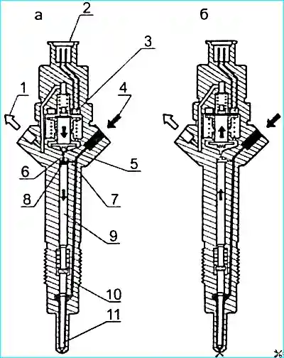
1 — fuel return line; 2 — electrical connection terminals; 3 — solenoid valve; 4 — high pressure line; 5 — valve ball;
6 — fuel outlet throttle opening; 7 — fuel supply throttle opening; 8 — control valve chamber; 9 — control valve piston;
10 — fuel supply channel to the sprayer; 11 — needle and sprayer
Injector operating principle:
- When throttle opening 6 is closed, the hydraulic force acting from above on the control valve piston exceeds the fuel pressure force from below on the needle cone — the needle is pressed, no injection occurs.
- When solenoid valve 3 is activated, throttle opening 6 opens, pressure in the control valve chamber decreases, the needle moves away from the seat — fuel is injected into the combustion chamber.
- The amount of injected fuel is proportional to the solenoid valve activation time and the pressure in the rail.
Coarse Fuel Filter "Pre Line 270"
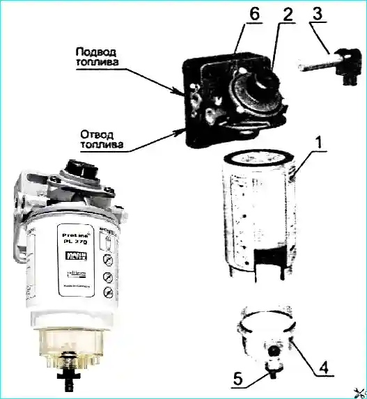
1 — coarse fuel filter; 2 — manual fuel priming pump; 3 — fuel heater; 4 — moisture separator; 5 — water drain valve; 6 — air release plug
Filter features:
- Sludge is drained through valve 5 at the bottom of moisture separator 4.
- When operating at temperatures below -25°C, the filter housing must be equipped with heater 3 (24 V, 350 W). The heater operates autonomously, turning on and off automatically at temperatures below +5°C.
Fine Fuel Filter
The fine fuel filter is used for final fuel purification. The filter is non-serviceable. Fuel passing through the paper filter element curtains is cleaned of mechanical impurities.
Air Supply System
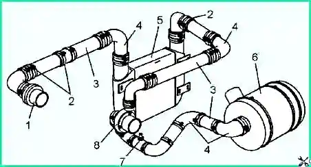
1 — air supply pipe; 2 — clamps; 3 — pipe; 4 — branch pipe; 5 — charge air cooler; 6 — filter;
7 — filter clogging sensor-indicator; 8 — turbocharger
Attention! Unfiltered air entering the engine cylinders due to intake tract depressurization leads to a sharp reduction in engine service life.
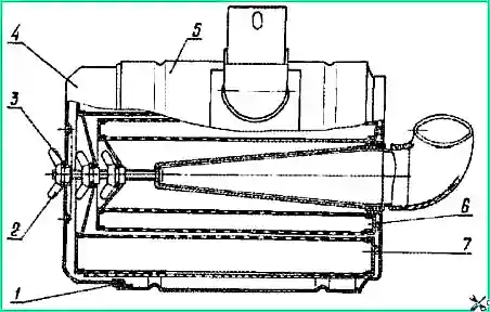
1 — sealing ring; 2 — wing nut; 3 — washer; 4 — cover; 5 — body; 6 — control filter element; 7 — main filter element
Air filter: Dry type with replaceable paper filter elements. The small (inner) filter element ensures air purification in case of mechanical failure of the outer filter element.
Clogging monitoring: A sensor is installed between the filter and turbocharger. As the filter becomes clogged, vacuum increases, and when it reaches 6.5 kPa, the "Air filter clogged" warning lamp lights up on the instrument panel. When the lamp lights up, clean or replace the filter element.
Turbocharger
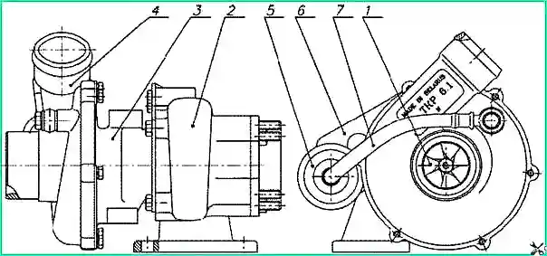
1 — rotor; 2 — turbine housing; 3 — bearing housing; 4 — compressor housing; 5 — actuator; 6 — actuator mounting bracket;
7 — air duct
Turbocharger design: Consists of a single-stage centrifugal compressor and a radial centripetal turbine. Boost pressure is regulated by bypassing part of the exhaust gases past the turbine wheel when boost pressure exceeds a certain value.
Important!
- Changing the actuator rod length of the turbocharger during operation is not permitted.
- Disassembly and repair of the turbocharger during operation are not permitted and must be performed at a specialized repair workshop.