Clutch Overview
Clutch (Fig. 1) single-plate diaphragm type with a damper device on the driven disk. The clutch pressure is generated by the disc pressure spring.
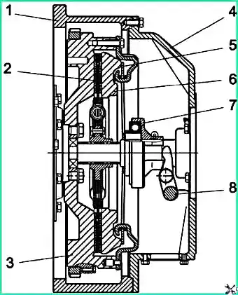
There is no gap between the pressure spring and the release bearing, so the inner race of the bearing rotates at the engine speed. During operation, the clutch does not require adjustment.
The clutch pedal rotates in the body bracket on a plastic bushing. The bushing is not lubricated. In the uppermost position, the pedal is held by spring 3. In this case, the pedal rests against rubber buffer 2.
Lubrication points:
- The ends of the clutch fork, moving in the hole in the clutch housing and in the bushing, are lubricated through two grease nipples.
- The release bearing does not require lubrication.
- Lubricant is added (replaced) into the cavity of the release bearing coupling when performing related repairs, or during seasonal maintenance (in fall), as well as in case of deterioration in the mobility of the coupling.
Clutch Release Drive of PAZ-32053-07 Bus (Hydraulic)
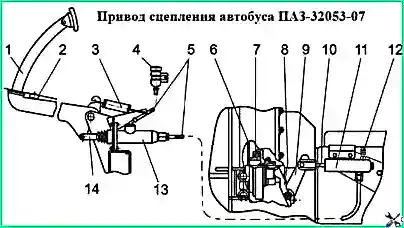
1 — pedal; 2 — pedal buffer; 3 — spring; 4 — reservoir; 5 — pipelines; 6 — pressure spring; 7 — bearing;
8 — fork; 9 — lever; 10 — pusher with fork; 11 — slave cylinder; 12 — bleeder valve; 13 — master cylinder; 14 — pusher fork
Operation principle: Master cylinder (13), mounted on a bracket under the driver's floor, is activated by pedal (1). To remove air from the system, slave cylinder (11) has a bleeder valve that is closed with a rubber cap.
When pedal (1) is not pressed, the cavity under the piston of the master cylinder (13) communicates with reservoir (4) through a compensation hole, which eliminates an increase in pressure in the hydraulic system and clutch slipping.
Automatic adjustment: A spring located inside the slave cylinder constantly presses the clutch release bearing against the clutch pressure spring. When the clutch linings wear, excess fluid from the slave cylinder enters the reservoir through the compensation hole. The available length reserve of the slave cylinder for piston movement ensures the calculated wear of the clutch linings without adjustment.
Drive adjustment: Should ensure free play of the clutch pedal of 7–8 mm, which corresponds to a gap of 1 ± 0.5 mm between the pusher and the piston of the clutch master cylinder. The length of the clutch master cylinder piston pusher is adjusted by turning the pusher fork. After adjustment, tighten the locknut and install the master cylinder protective cap.
When repairing the clutch slave cylinder and replacing parts, check and if necessary adjust the length of the slave cylinder piston pusher. The length from the center line of the hole on the fork to the end of the pusher ball joint should be 150 ± 1 mm.
Filling (Bleeding) the Hydraulic Clutch Drive
- Unscrew the cap of the filler reservoir, remove the plug reflector and fill the reservoir with brake fluid to two-thirds of its height.
- On the clutch slave cylinder, remove the cap from the bleeder valve and place a rubber hose (about 500 mm long) onto the valve. Place the free end of the hose into a transparent container with brake fluid (fill to half the container height).
- Create pressure in the system by sharply pressing the clutch pedal 3–4 times at intervals of 3–5 seconds.
- Keeping the pedal pressed, unscrew the bleeder valve 1/2–3/4 turn, making sure the end of the hose remains immersed in the fluid. Fluid with air bubbles will escape into the container.
- After fluid stops flowing, turn the valve fully in, then release the pedal. During bleeding, add working fluid to the reservoir, avoiding a "dry bottom".
- Repeat the bleeding operations until fluid comes out without air bubbles.
- Keeping the pedal pressed, turn the bleeder valve fully in and smoothly release the pedal.
- Remove the hose and put on the rubber cap.
- Add fluid to two-thirds of the reservoir height, install the reflector and reservoir cap.
Clutch Release Drive of PAZ-4234 Bus (Hydropneumatic)
The clutch release drive of the PAZ-4234 bus can be hydropneumatic. The pneumatic hydraulic booster (PGU) is installed in a complete set with a ZF SACHS clutch (Germany). PGU units manufactured by KAMAZ or Knorr-Bremse (Germany) are used.
PGU is designed to reduce the force on the clutch pedal when pressed. The PGU operates effectively when air pressure in the bus pneumatic system is 0.6–0.8 MPa.
Warning! The full travel of the clutch pedal is limited by setting the pedal travel limiter. Operating a bus without a clutch pedal travel limiter will result in clutch failure.
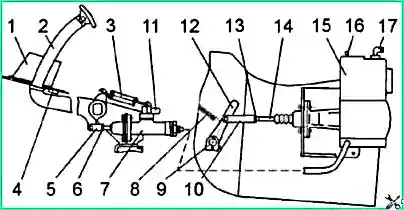
1 — pedal travel limiter; 2 — pedal; 3 — spring; 4 — pedal stop; 5 — master cylinder fork; 6, 13 — lock nut;
7 — master cylinder; 8 — pressure spring; 9 — fork shaft; 10 — PGU pusher fork; 11 — pipeline to reservoir;
12 — clutch fork lever; 14 — PGU pusher; 15 — PGU; 16 — bypass valve; 17 — pneumatic tube fitting
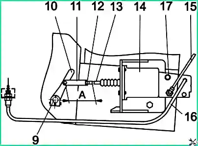
9 — fork shaft; 10 — clutch fork lever; 11 — PGU pusher fork; 12 — lock nut; 13 — PGU piston pusher;
14 — PGU; 15 — pneumatic pipeline; 16 — hydraulic pipeline; 17 — bypass valve;
A — control size equal to 186–189 mm
Adjustment of clutch release drive with PGU should ensure free pedal play of 3–10 mm.
- Knorr-Bremse PGU: Free play of the clutch fork lever is adjusted automatically. Pedal free play is adjusted by changing the master cylinder piston pusher length.
- KAMAZ PGU: Free play of the clutch fork lever is additionally adjusted.
Adjusting free play of the clutch fork lever (KAMAZ PGU only):
- Check the free play of the fork lever by rocking the lever in both directions. Free play should be 1 ± 0.5 mm.
- Remove pressure spring (8) of the clutch fork lever.
- Loosen locknut (13) of the PGU rod.
- Change the pusher rod length by rotating the fork along the rod thread.
- Tighten the locknut and install the pressure spring.
After complete adjustment of the clutch drive (the pedal travel limiter must be installed), the working stroke of the PGU pusher should be 16.5–19.0 mm.
Maintenance of clutch with KAMAZ PGU:
- Check free play of the fork lever at every maintenance-1 (TO-1).
- At every maintenance-2 (TO-2), check the pressure spring characteristic. Permissible force when stretched to 130 mm must be at least 75–90 N. Replace if less.
Installing Knorr-Bremse PGU: During repair, rotate the fork on the PGU pusher rod so that the distance from the fork hole axis to the annular groove on the PGU piston pusher equals 186–189 mm. Tighten the locknut. The PGU pusher working stroke should be 16.5–19.0 mm.
Installing the clutch fork lever: Align the marks on the clutch fork shaft end and on the lever body to ensure proper lever position.
Release bearing clutch lubrication: If movement is difficult, or once a year during seasonal maintenance, or during gearbox removal repair, clean the cover surface and replace/add Optimal Olista LongTime 3 EP lubricant to the release bearing clutch cavity.
Filling the clutch hydraulic drive with PGU: Same as on PAZ-32053-07, but the bypass valve is on the PGU body, and the PGU must be connected to compressed air at 0.6–0.8 MPa.
Possible Clutch Malfunctions and Elimination Methods
Incomplete clutch engagement (clutch "slips")
Symptoms: Burning smell, reduced acceleration and speed
- Oil on friction linings (from engine or gearbox) — Fix oil leak. Replace driven disc or linings. If slight, wash linings with gasoline and sand lightly.
- Excessive wear of driven disk linings — Replace driven disk or friction linings.
Incomplete clutch disengagement (clutch "drives")
Symptoms: Difficult gear shifting, grinding noise when changing gears
- Air in clutch hydraulic drive — Bleed the hydraulic system.
- Worn master cylinder inner seal — Replace the seal.
- Driven disk deformation — Replace or straighten the driven disk (face runout relative to hub spline ≤ 0.7 mm).
- Driven disk hub jamming on input shaft splines — Remove jamming.
- Front bearing jamming of gearbox input shaft (in flywheel) — Replace the bearing.
Fluid leakage from clutch master or slave cylinder
- Worn master cylinder outer seal or slave cylinder seal — Replace worn seals or replace the cylinder.
")

")
")
")
")
")
")
")