The electrical equipment system of the bus is single-wire, the negative terminals of the current sources are connected to the body (“ground”) of the bus. Rated voltage 12V
The power sources on the bus include a battery and an alternator with a built-in rectifier.
The generator is connected in parallel with the battery.
The installation provides power to consumers in any engine operating mode, as well as recharging batteries.
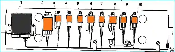
The electrical equipment relay block is located on the panel under the casing above the driver's door (Fig. 1).
The generator excitation circuit unloading relay 90.3747 is located in the engine compartment near the generator.
The 6ST-100 battery (abbr. battery) with a voltage of 12V and a capacity of 100 Ah is installed in the battery box located on the right side of the body behind the passenger door.
The use of imported batteries with similar characteristics is allowed.
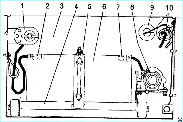
The battery box has two battery switches: one pos. 8 (Fig. 2) - disconnecting the “battery”, with remote control from the button on the instrument panel; the other - pos. 1 - shutdown “- battery” with mechanical shutdown.
When you turn off the “+ battery” button on the instrument panel, the alarm system, emergency switch power supply, door mechanism control, and liquid heater are not turned off.
To completely disconnect the battery, you need to turn the handle of mechanical switch 1.
Attention! When parking the bus for a long time, it is necessary to turn off the “- battery” with a mechanical switch.
Attention! When turning off the “+ battery” button located on the instrument panel, it is prohibited to hold the button pressed for more than 2 seconds.
In an emergency, the battery can also be switched off using the emergency switch. The emergency switch can have three key positions:
- - I - switched off, while the button is not pressed and is fixed with a locking flag (movement mode);
- - II – mode of turning off the “+ battery” and turning off the alarm; to do this, turn the latch flag and press the button until it is in a fixed position;
- - III - switching off the battery is done by pressing the switch key to the extreme (not fixed position). After you stop pressing the key returns to position II.
When turning “+ battery” on and off using the button on the instrument panel (as well as when turning on the emergency switch), you should pay attention to the occurrence of two characteristic clicks from the operation of the electromagnet of the remote switch.
If only one click occurs, you need to check the condition of the switch button on the instrument panel (forcibly pull it out of the switch body), after which a second click will occur from the operation of the remote switch, which corresponds to the normal operation of the “+ battery” switch.
Attention! It is prohibited to turn off the battery switch while the engine is running and consumers are turned on.
Fuses
All bus power supply circuits are protected by fuses.
The bus has three fuse blocks: one block of “power” fuses BPR-5-4. located in the battery box on the right side and two PR112 fuse blocks located near the steering column.
Power fuses
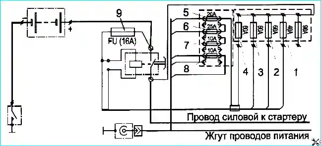
Item number - Current A - Wire color - Purpose:
- - 40 - yellow - side lights;
- - 60 - red - fuse blocks, headlights, ignition switches;
- - 60 - white - not used;
- - 60 - blue - fuse block;
- - 20 - pink - ABS;
- - 25 - brown - heater;
- - 10 - white - emergency mode;
- - 10 - purple - battery box socket;
- - 16 - white - winding of the "-battery" switch
If there are no factory-made fuse links, it is allowed to temporarily use copper wire Ø 0.23 mm for insert 8A, and Ø 0.34 mm for insert 16A, until they are replaced.
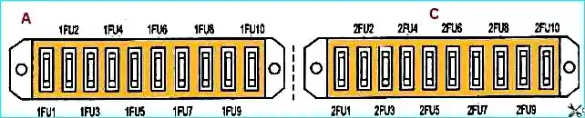
Bus fuses and protected circuits
Designation (Current Strength) - Protected Circuits
Left fuse block
- 1FU1(8A) - Passenger door drive control switch. Power supply for turn signal and door alarm systems.
- 1FU2 (8A) - Power supply for driver's lamp switch, emergency switch
- 1FU3(16A) - Power supply for devices, ABS unit, ignition system
- 1FU4(8A) - Power supply for indicator lamps, reversing light switch
- 1FU5(8A) - Power supply for left windshield wiper
- 1FU6(8A) - Power supply for circulation pump
- 1FU7(8A) - Power supply for windshield washer switch, instrument cluster and voltmeter
- 1FU8(16A) - Power supply for fog lights
- 1FU9(8A) - Power supply for side lights on the right side
- 1FU10 (8A) - Power supply for left side parking lights
Right fuse block
- 2FU1(16A) - Power supply for sound signal relay, air dryer
- 2FU2(16A) - Power supply for the windshield blower switch
- 2FU3(16A) - Power supply for the interior lamp switch, engine compartment lamp and socket
- 2FU4(8A) - Power supply for the right side interior lamp switch
- 2FU5(8A) - Power supply for left headlight "High beam"
- 2FU6(8A) - Power supply for the right headlight "High beam" Power supply for the indicator lamp "High beam"
- 2FU7(8A) - Power supply for the left "Low beam" headlight, rear fog lamp switch
- 2FU8(8A) - Power supply for the right “low beam” headlight
- 2FU9(8A) - Power supply for right windshield wiper, brake lights
- 2FU10(8A) - Spare
The bus diagrams are presented in the article “Wiring harness diagrams for the PAZ-32053 bus”