The numbering order of the engine cylinders is shown in Fig. 1

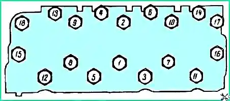
Tightening the nuts securing the cylinder heads to the block is carried out on a cold engine in the order shown in Figure 2.
Tightening should be done with a special torque wrench with a tightening torque of 75 - 80 Nm (7.7 - 8.2 kgf.m).
Before tightening, unscrew the nuts of the rocker arm axle struts and, by lifting the struts together with the axle, provide access to the cylinder head fastening nuts.
After tightening the cylinder head nuts, re-tighten the loosened nuts. After this, it is necessary to adjust the gaps between the valves and rocker arms.
Tighten the nuts of the head mounting studs during the first three TO-1s, and then perform this operation through one TO-2.
Tightening the nuts of the intake pipe, as well as installing it in place after disassembly, must be done with great care to avoid water leakage into the oil.
Before installation, you should check the condition of the mating planes of the intake pipe, heads and block, as well as gaskets.
First you need to tighten the nuts so as to lightly press the gaskets.
Then you need to tighten the cylinder head load nuts.
After tightening the weight nuts, it is necessary to tighten the intake pipe mounting nuts alternately on the left and right sides, starting from the weight nuts.
Piston rings are replaced when oil consumption increases by more than 0.4% of operating fuel consumption without taking into account lubricant changes.
Piston rings are installed three on each piston: two compression rings and one oil scraper ring.
Compression rings are installed so that the groove (if any) on the inner surface of the rings faces upward.
When installing compression rings on the piston, the joints of the rings must be offset by 180° relative to each other.
Flat annular disks of the oil scraper ring are installed so that their locks are located at an angle of 180° to one another and at an angle of 90° to the locks of the compression rings.
In this case, the locks of the axial expander and radial expander must be located at a 90° angle to the locks of the flat disks.
When replacing rings, the unworn protruding band in its upper part should be removed from the sleeve (using a scraper or other means).
At the same time, the cylinder heads and piston heads should be cleaned of carbon deposits, the cavity of the water jacket should be cleared of scale, and the valves should be ground in.
The main bearing shells are replaced when the oil pressure drops on a warm engine below 100 kPa (1.0 kgf/cm) at 1200 rpm, which corresponds to a direct drive speed of 35 - 40 km/h.
The oil cooler must be turned off when monitoring oil pressure.
Driving with oil pressure less than 100 kPa at the indicated speed and higher is not allowed.
The protrusion of the sleeves above the plane of the block is 0.02 - 0.1 mm. The difference in protrusion at different points of one sleeve should not exceed 0.04 mm.
Gas distribution mechanism
Checking and adjusting the gap between valves and rocker arms
Checking the valve clearance is performed in the following sequence:

- - remove the rocker covers;
- - unscrew the spark plug of the first cylinder;
- - set the piston of the first cylinder at the top dead center (TDC) of the compression stroke.
To do this, you need to close the hole for the spark plug of the first cylinder with your finger and turn the engine crankshaft with the starting handle until air begins to escape from under your finger.
This will happen at the beginning of the compression stroke in the first cylinder.
- slowly turn the crankshaft until the mark on the crankshaft pulley coincides with the middle protrusion on the camshaft cover.
When the piston of the first cylinder is positioned at TDC. During the compression stroke, the intake and exhaust valves are completely closed.
- check the gap using a feeler gauge. The gap between the rocker arm and the valve stem should be 0.20-0.30 mm on a cold (15-20˚ C) engine.
It is allowed to reduce the gap to 0.15-0.20 mm for valves located at the edges of the heads: the first and eighth intake, fourth and fifth exhaust.
If necessary If possible, you need to adjust the gap in the following sequence:
- - loosen the locknut of the adjusting screw (Fig. 3-3); turn the adjusting screw with a screwdriver to set the gap on the feeler gauge;
- - tighten the locknut of the adjusting screw and check the clearance again.
Then you should check and, if necessary, adjust the valve clearances of the remaining cylinders in the sequence corresponding to the operating order of the cylinders (1-5-4-2-6-3-7-8), turning the crankshaft when moving from cylinders to cylinder at 90°.
- - install the rocker covers in place;
- - wrap the spark plug of the first cylinder;
- - start the engine and listen to its operation.
When the engine is running, a subtle knocking sound of valves may be heard in some operating modes. There should be no “sneezing” in the carburetor and “shots” in the muffler.
On a running hot engine, due to uneven temperatures of various parts in some engine operating modes, valve knocking can sometimes be heard, which may either decrease over time or reappear.
Such a subtle knock is not dangerous and in this case there is no need to reduce the gap between the valves and rocker arms.
If, on a warm engine, the knocking of valves is heard continuously, which is more often observed with valves located at the edges of the heads, then in this case, for these valves it is possible to reduce the clearance so that on a cold engine it is in the range of 0.15-0 .20 mm.
")

")
")
")
")
")
")
")