General Information on Inspecting Brake Mechanisms
The condition of the brake drums, shoes, and brake linings is checked at every TO-2.
Checking Lining Wear: The remaining thickness of the brake linings can be checked through the inspection windows in the brake drums or in the brake lining shields. If the lining thickness is less than 5 mm, remove the brake drum and assess the wear using the distance from the rivet to the lining surface.
Before removing the rear brake drums, release the parking brake.
Bringing the shoes together when removing the drum: If the brake drum does not come off the shoes due to a lip formed by wear on the drum, the shoes must be pulled together. To bring the shoes together, turn the brake adjuster screw to rotate the adjusting lever in the direction opposite to the brake chamber piston stroke during braking.
Inspection and Repair of Brake Drums
Drum Condition Requirements: Brake drums must be free of cracks and chips. If deep scoring, scratches, or wear over a diameter greater than 0.5 mm is detected on a brake drum, such drums should be bored to one of the nearest repair sizes.
Brake Drum Repair Sizes
| Axle | Condition | Shoe Outer Surface Diameter, mm | Inner Drum Diameter, mm |
|---|---|---|---|
| KAAZ | Nominal | 379.6 -0.60 | 380.5 +0.36 |
| First Repair | 380.6 -0.60 | 381.5 +0.36 | |
| Second Repair | 381.6 -0.60 | 382.5 +0.36 | |
| Third Repair | 382.6 -0.60 | 383.5 +0.36 | |
| Fourth Repair | 383.6 -0.60 | 383.5 +0.36 | |
| RAA | Nominal | 420 -0.4 | 420 +0.38 |
| First Repair | 421 -0.4 | 421 +0.38 | |
| Second Repair | 422 -0.4 | 422 +0.38 | |
| Third Repair | 423 -0.4 | 423 +0.38 | |
| Fourth Repair | 424 -0.4 | 424 +0.38 |
Limiting Drum Dimensions:
- If, after machining, the drum's internal diameter exceeds 384.5 mm for KAAZ axles and 424 mm for RAA axles, the drum must be replaced.
- The maximum diameter of the brake drum's working surface, upon reaching which bus operation is prohibited, is: 386 mm for KAAZ axles, 426 mm for RAA axles.
Boring Technology: The brake drum must be bored as a complete unit with the hub, centered on the outer bearing rings pressed into the hub. The runout of the machined drum surface must not exceed 0.25 mm.
Inspection and Replacement of Brake Shoes and Linings
Requirements for the condition of shoes and linings:
- Brake shoes must not have any mechanical damage.
- Friction linings must not have chips or cracks extending through rivet holes or exceeding 15 mm.
- If the lining surfaces become oily, they must be replaced.
- If a lining wears to 0.5 mm above the rivet, the lining is rejected. This distance must be at least 2 mm for a standard brake shoe.
Important requirements for replacement:
- It is not permitted to install brake shoes with different lining materials on the brake mechanisms of the same axle.
- Do not replace only one brake shoe or lining on one side of the bus. If it is necessary to replace one or both linings on one wheel, it is better to do this on both sides of the bus axle to prevent it from pulling to the side when braking.
- New linings must provide a clearance between the drum and the lining of at least 0.3 mm.
Replacing Brake Shoes (PAZ-32053-07, KAAZ Axles)
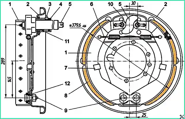
1 — shoe; 2 — shield; 3 — expander knuckle grease nipple; 4 — sealing ring; 5 — expander knuckle;
6 — tension spring; 7 — guide bracket; 8 — lining; 9 — shoe support pin; 10 — roller; 11 — knuckle support bushing; 12 — pin bushing
Replacement Procedure:
- Place the bus on an inspection pit. Loosen the wheel rim nuts. Raise the wheel with a jack, install wheel chocks and a sturdy, stable support under the axle. Release the parking brake.
- Loosen the wheel rim nuts and remove the wheel.
- Depress the brake adjuster lock and turn it to the left with a wrench until the expander knuckle returns to its original position, then loosen the 9 shoe support pin nuts and turn the pins so the marks are facing inward. After this, the gap between the lining and the drum will be at its maximum.
- Remove the drum, tension springs 6, unscrew the support pin nuts, and remove the brake shoes 1.
- Install the shoes with new linings on the brake shield using the support pins with bushings. Pre-lubricate the surface of bushing 12 with a thin layer of Litol-24 grease. The marks on the heads of pins 9 should face inward.
- Align the shoes relative to the drum by rotating the support pins to ensure proper contact between the shoes and the drum. The gap between the lining and the drum should be (0.5–0.9) mm. The rotation angle of the support pin should not exceed ±40° from the position with the marks inward.
- Tighten the support pin nuts.
- Turn the brake adjuster lock to the right until it stops (until the shoes touch the drum), then turn the lock to the left by (120–180)°. Release the lock. If the latch remains recessed, rotate it left and right within 30° until it returns to its original position.
Replacing Brake Shoes (PAZ-4234, KAAZ Axles)
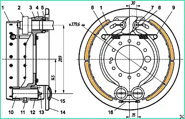
1 — shoe; 2 — expander fist; 3 — bushing; 4 — brake mechanism support; 5 — sealing ring;
6 — tension spring; 7 — shoe roller; 8 — roller retainer; 9 — spring axis; 10 — shoe axis; 11 — lock bolt;
12 — bushing; 13 — grease nipple; 14 — protective shield; 15 — plug; 16 — locking wire
Replacement Procedure:
- Perform the preparatory operations (items 1-3 of the previous section), remove the drum and spring.
- Remove locking wire 16, unscrew locking bolts 11, and knock out shoe axles 10.
- Install the shoes with fitted new linings on the caliper using support axles 10 with bushings 12. Pre-lubricate the surface of the bushings with a thin layer of grease. When installing locking bolts 11, ensure they engage the flats of axles 10. Secure the locking bolts with locking wire 16.
- Install the shoe tension spring and brake drum. Before installing the drum on the hub, apply a thin layer of graphite grease to the mounting surface.
- Lubricate the brake shoe axles using grease fittings 13 until fresh grease emerges from the gaps.
- If the brake shoes were replaced with the hub removed, after installing the hub, carefully pull the ABS wheel sensor out until it contacts the hub ring gear, then rotate the hub 2-3 turns to achieve the required clearance.
Replacing Brake Shoes (RAA Axles)
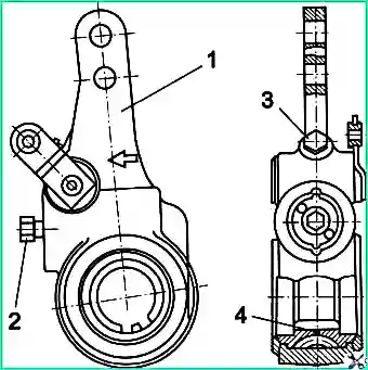
1 — regulator body; 2 — locks; 3 — plug; 4 — grease outlet hole
Replacement Procedure:
- Depress lock 2 of the brake regulator and rotate the wrench counterclockwise until the expanding cam returns to its original position. This will maximize the gap between the lining and the drum.
- Remove the hub together with the drum.
- Remove the tension springs and brake shoes.
- Remove the brake shields for easier adjustment.
- Loosen the nuts securing the eccentric axles (support pins) of the shoes. Bring the eccentrics closer together, aligning the axles with the marks facing each other.
- Loosen the nuts and bolts securing the brake chamber brackets.
- Loosen the bolts securing the rear brake cam support.
- Apply compressed air to the brake chamber at a pressure of 0.1–0.15 MPa (1.0–1.5 kgf/cm²) or, if there is no air, remove the piston rod pin and press the adjusting lever in the direction of piston rod travel during braking to press the shoes against the drum.
- Center the shoes relative to the drum by rotating the eccentrics to ensure proper contact between the shoes and the drum. At a distance of (20–30) mm from the outer ends of the linings, a 0.1 mm feeler gauge should not pass along the entire width of the lining.
- Without stopping the air supply (or without releasing the lever), tighten the axle nuts, brake chamber bracket mounting bolts, and expander cam bearing bolts.
- Stop the air supply (release the lever), attach the brake chamber piston rod, and install the shields.
Preliminary Adjustment of the Brake Regulator (After Replacing the Shoes)
- Release the energy accumulators.
- Install the regulator on the brake drive shaft and secure it. The direction of the brake chamber force must match the direction of the arrow on the housing.
- Push the locking pin 2 into the regulator until it stops. While holding the locking pin, use the wrench to turn it to the right until the holes in the regulator housing and the brake chamber fork align.
- Connect the regulator housing to the brake chamber fork and install the drive rod.
- Turn the locking pin to the right until it stops (until the shoes touch the drum), then turn the locking pin to the left by (120–180)°. This will set the clearance close to the desired value.
- Release the locking pin. If it remains recessed, rotate it left and right within 30° until it returns to its original position.
Brake System Control Parameters:
- The stroke of the brake chamber piston at an operating pressure of (0.7–0.8) MPa should be within (30–40) mm.
- The difference in piston stroke between the right and left chambers should not exceed 5 mm.
Maintenance of the RT-40 Brake Regulator: The regulator is non-disassemblable. Add (40–50) g of ZhT-72 grease every 60,000 km by pumping it through the hole closed by plug 3.
Caution! Using Litol-24 grease in the brake regulator will cause the regulator to malfunction.
Caution! To prevent the rear brake shoes from freezing to the drums after prolonged parking in extreme temperature fluctuations, it is not recommended to leave the bus with the parking brake engaged without drying the brakes by gently braking while driving.
Lubricating the Camshaft Bearings: Perform this until fresh grease appears from the gaps between the camshaft and the bracket.
")

")
")
")
")
")
")
")