The diesel fuel supply system (Fig. 1) consists of a high pressure fuel pump 4, injectors 13, low 6 and high 9 pressure pipelines, intake 12 and exhaust manifolds, coarse 3 and fine 10 fuel filters, fuel tank 1, pipelines and hoses
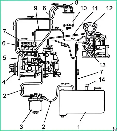
Power system diagram: 1 - fuel tank; 2 - suction pipeline; 3 - fuel coarse filter; 4 - high pressure fuel pump; 5 - booster pump; 6 - low pressure pipeline; 7- drain pipeline; 8 - fuel system bleeding plug; 9 - high pressure pipeline; 10 - fine fuel filter; 11 - pneumatic corrector tube; 12 - inlet pipe; 13 - nozzle; 14 - excess pressure valve in the tank
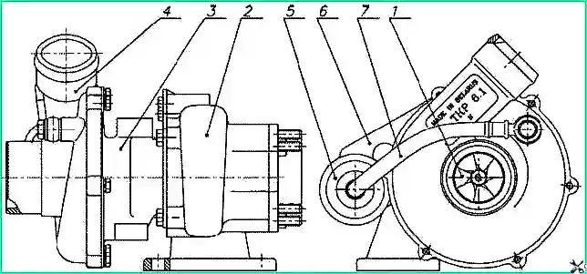
The high-pressure fuel pump (hereinafter abbreviated as injection pump, Fig. 2) is designed to supply metered portions of fuel under high pressure into the combustion chambers of diesel cylinders at certain times to provide the required power.
These portions of fuel must be the same for all sections of the fuel injection pump.
Diesel engines are equipped with fuel injection pump mod. 773-20.06 (for D-245.9E2) and injection pump mod. 773-20.05 (for D-245.7E2) manufactured by JSC "YAZDA".
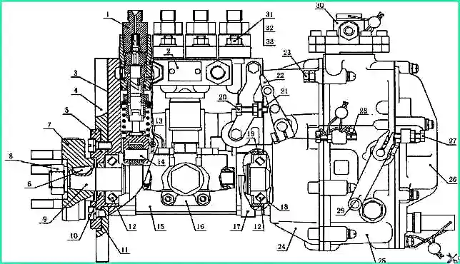
High pressure fuel pump: 1- section of the fuel pump; 2 - plate; 3 - flange gasket; 4 - flange; 5 - bearing cover; 6 - key; 7 - drive coupling half; 8 - nut for fastening the coupling half; 9 - cam shaft; 10 - bearing cover cuff; 11 - bearing cover gasket; 12 - bearing; 13 - pusher guide pin; 14 - pusher; 15 - fuel pump housing; 16 - fuel priming pump; 17 - stud of the fuel injection pump support bracket; 18 - adjustment parameters; 19 - bearing ring; 20 - bolt; 21 - bracket; 22 - stop lever; 23 - bolt; 24 - regulator body; 25 - regulator cover; 26 - inspection hatch cover; 27 - minimum rotation speed adjustment bolt; 28 - bolt for adjusting maximum rotation speed; 29 - control lever; 30 - boost corrector; 31 - hairpin; 32 - nut; 33 - washer
The injection pump is combined into one unit with an all-mode regulator 25 and a piston-type booster pump 16.
The regulator is used to control the fuel supply by the fuel pump depending on the rotational speed (load) of the diesel engine. At the same time, it protects the diesel engine from runaway when the load drops.
The regulator has a fuel supply corrector, an automatic fuel enricher operating at starting speed, and an anti-smoke pneumatic corrector 30.
The pneumatic corrector is designed to reduce the fuel supply when the diesel engine speed is reduced in order to reduce smoke.
At the same time, it serves as a stop that prevents an increase in fuel supply when the fuel control pedal is sharply pressed when the diesel turbocharger still supplies a small amount of air due to the low speed of the diesel engine.
Double-arm excess corrector lever
pressure engages with the rod of the fuel pump control rack under the influence of lubricating oil pressure from the diesel lubrication system.
The change in air pressure supplied from the diesel inlet pipeline to the pneumatic corrector diaphragm is transmitted using a double-arm lever to the rod tooth with the control rack spring.
In this way, the amount of fuel supplied to the fuel pump is adjusted.
The working parts of the fuel pumps are lubricated with flowing oil coming from the diesel lubrication system into the pump housing through a special hole in the flange.
Oil is drained from the pump housing into the diesel crankcase through a special drilling in the flange. Before installation, the pump must be filled with oil in the amount of (200-250) cm 3.
The filler hole is located in the pump flange 4.
All adjustments to the high-pressure pump and its disassembly to replace parts are carried out in a special workshop by highly qualified specialists.
The bypass valve is used to create the required pressure (0.12-0.19) MPa in the low pressure channels of the injection pump.
Excess fuel supplied by the fuel priming pump goes to the drain through the bypass valve.
When the engine is not running, the bypass valve ensures the tightness of the low-pressure cavity of the injection pump, which is a necessary condition for reliable engine starting.
The injector is designed to inject fuel into a diesel cylinder, ensuring the required fuel atomization and limiting the start and end of the supply.
Diesel engines use a nozzle with axial fuel supply and a five-hole closed-type spray nozzle 455.1112010-50 (JSC "YAZDA") or 172.1112010-11.01 produced by JSC "AZPI".
The injector is marked “455-10”, and the injector nozzle is marked “335-120”. The marking is applied to the nozzle body and the atomizer body.
Disassembly and adjustment of the nozzle are carried out on a special stand in the workshop by qualified specialists.
Low-pressure piston-type fuel pump, designed to supply fuel from the tank through coarse and fine filters to the injection pump.
The pump is installed on the injection pump housing and is driven by the eccentric of the injection pump cam shaft.
When the engine is not running, the fuel priming pump is operated by hand to fill the power system with fuel and remove air from it before starting the diesel engine.
Pumping is carried out by moving the handle up and down.
Attention! Do not operate the fuel system with a clogged fuel filter.
The fuel supply control drive is mechanical, consisting of a pedal connected by a rod to the high-pressure fuel pump rack control lever.
Pedal travel all the way to the floor mat should ensure rotation of the fuel pump rack control lever until fuel is fully supplied.
If necessary, adjust the position of the pedal by changing the length of the rod, having previously loosened the nuts.
After adjustment, the nuts must be locked.
When the lever is moved to its extreme position back (towards the flywheel), the diesel engine develops maximum rotation speed. When the lever is in the extreme forward position, the fuel supply stops.
To shut off the fuel supply, a pneumatic cylinder is used, which is controlled by an electrical signal from the ignition switch. The cylinder rod acts on the fuel injection pump stop lever.
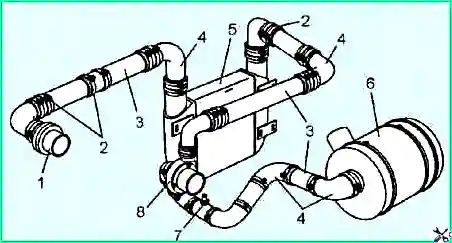
Engine air supply system: 1 - air supply pipe; 2 - clamps; 3 - pipe; 4 - pipe; 5 - charge air cooler; 6 - air filter; 7 - filter clogging indicator sensor; 8 - turbocharger
The diesel air supply system (Fig. 3) consists of an air filter, a turbocharger, a charge air cooler, pipes, pipelines and fastening clamps.
A dry type air filter with replaceable paper filter elements is used to clean the air entering the cylinders.
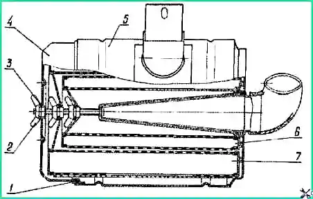
Air filter: 1- O-ring; 2 - wing nut; 3 - washer; 4 - cover; 5 - body; 6 - control filter element; 7- main filter element
The air filter (Fig. 4) consists of a housing 5, two filter elements 6 and 7, a cover 4. There are rubber gaskets to ensure tightness.
A small (internal) filter element ensures air purification in the event of mechanical destruction of the outer filter element.
Attention! The influx of untreated air into the engine cylinders, which occurs due to depressurization of the intake tract, leads to a sharp decrease in engine service life.
To facilitate monitoring of air filter clogging, a sensor is installed between the filter and the turbocharger, and an indicator is installed on the instrument panel.
As the filter becomes clogged, the vacuum in the intake pipe increases and when it reaches a value of 6.5 kPa, the warning light goes off and the “Air filter clogged” warning lamp lights up on the instrument panel.
When the lamp lights up, the filter element should be cleaned or replaced.
Turbocompressor: 1 - rotor; 2 - turbine housing; 3 - bearing housing; 4 - compressor housing; 5 - actuator; 6 - bracket for fastening the actuator; 7- air duct
The turbocharger (Fig. 5) consists of a centrifugal single-stage compressor and a radial centripetal turbine.
Boost control occurs by bypassing part of the exhaust gases past the turbine wheel when the boost pressure exceeds a certain value.
Attention! Changing the rod length of the turbocharger actuator is not allowed.
The turbocharger bearings are lubricated and cooled by oil supplied from the diesel lubrication system.
")

")
")
")
")
")
")
")