When repairing after disconnecting fuel lines, injectors and filters, all openings must be protected from dirt with plugs, caps, plugs or clean insulating tape
All parts must be thoroughly cleaned and washed in clean gasoline or diesel fuel before assembly.
Filling the power system with fuel and removing air is carried out after repair and maintenance of the power system, as well as after a long break in the operation of the diesel engine.
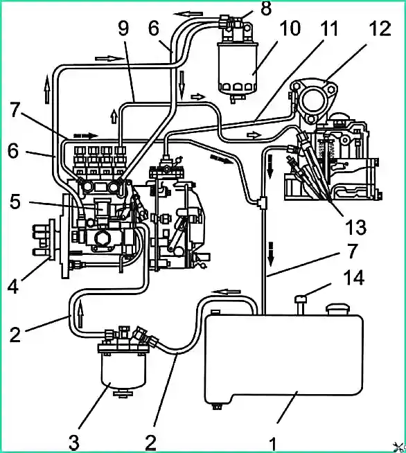
Power system diagram: 1 - fuel tank; 2 - suction pipeline; 3 - fuel coarse filter; 4 - high pressure fuel pump; 5 - booster pump; 6 - low pressure pipeline; 7- drain pipeline; 8 - fuel system bleeding plug; 9 - high pressure pipeline; 10 - fine fuel filter; 11 - pneumatic corrector tube 12 - inlet pipe; 13 - nozzle; 14 - excess pressure valve in the tank
To fill the fuel system, it is necessary to remove air from it (bleed the system), for which you need to unscrew plug 8 (Fig. 1), located on the bolt securing the outlet fitting of the fine fuel filter, by (2-3) turns and bleed the system with a booster pump 5 until clean (without air bubbles) fuel appears from under the fitting.
Then the plug is screwed in and the plug on the high pressure fuel pump housing is unscrewed.
The plug is located opposite the fourth section of the pump on the diesel block side.
Further pumping is carried out until clean fuel emerges from the fuel pump housing. After which the cork is wrapped.
Sludge is drained from the fuel coarse filter at each maintenance-1.
To drain the sediment, you need to unscrew the plug located at the bottom of the filter bowl and drain the sediment until clean fuel appears. Then screw the plug.
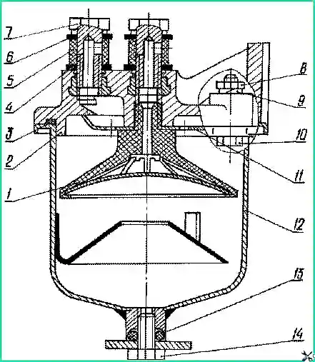
Coarse fuel filter: 1 - reflector with mesh; 2 - body; 3 - ring; 4, 6, 13 - sealing ring; 5 - protective sleeve; 7- rotary angle bolt; 8 - nut; 9 - washer; 10 - bolt; 11 - diffuser; 12 - glass; 14 - plug
Rinsing of the coarse fuel filter is carried out through one TO-2, for which you need:
- – unscrew the nuts of the bolts 10 (Fig. 2) securing the glass 12 and remove the glass;
- – unscrew the reflector with mesh 1 with a key and remove the diffuser 11;
- – wash the reflector with mesh, diffuser and filter cup in diesel fuel and install them in place.
After assembling the filter, fill the system with fuel.
Sludge is drained from the fine fuel filter at every maintenance-2.
To drain the sediment, you need to unscrew the plug located at the bottom of the filter bowl by (2-3) turns and drain the sediment until clean fuel appears. Then screw the plug.
Replacement of the fine fuel filter is carried out through one TO-2. To replace the filter:
- Clean the interface between the filter and the housing and unscrew the filter.
- Wipe the filter mating surface.
- Fill the new filter with clean fuel and install it complete with a gasket, which should first be lubricated with engine oil.
- After the gasket touches the housing cup, tighten the filter another 3/4 turn. Install the filter only by hand. Then remove air from the fuel system.
The service life of the filter element depends on the purity of the fuel used.
Maintenance of the fuel priming pump (abbr. FLP) is performed when servicing the injection pump on the adjustment stand.
To check the tightness of the fuel pump, air is supplied to the fuel suction line at a pressure of 4 kgf/cm 2. When the fuel injection line is closed, no air leaks are allowed for three minutes.
At a rotation speed of the injection pump camshaft n=1000 min -1, the performance of the injection pump must be at least 2.1 l/min. At n=1000 min -1 the maximum pressure with a completely closed section of the fuel injection pipe must be at least 0.4 MPa, and the vacuum should be at least 0.052 MPa with a completely closed section of the suction fuel line.
If these requirements are not met, it is necessary to completely disassemble the fuel pump, replace worn or failed parts, grind in or replace plastic valves.
The TPN may have the following malfunctions:
- The introduction of solid particles into the heads of plastic valves, wear of the sealing surfaces, leading to loss of tightness between the seat and the valve.
- Failure of the piston spring.
- Piston jammed in the fuel pump housing.
- Stem jammed in bushing.
All these malfunctions are a consequence of the use of low-quality fuel with a high content of sulfur, mechanical impurities and water.
Maintenance of the high pressure fuel pump (HPF)
During the operation of the injection pump, when the main parts wear out, the adjustable parameters of the pump are violated.
The required oil level in the pump crankcase is set automatically. It is necessary to ensure that the oil supply and drainage from the injection pump are in good condition.
If the oil supply hole is clogged, the injection pump will fail.
To reduce wear of precision parts, it is not allowed to operate the injection pump without a filter element or with a clogged fine fuel filter.
Working with fuels that have a high water content is also not allowed.
If necessary, and also every 120 thousand km, it is necessary to remove the fuel injection pump from the engine and check it on a stand for compliance with the adjustment parameters.
You should also check the fuel injection timing angle. If necessary, make appropriate adjustments.
Checking and adjusting the injection pump must be carried out by qualified personnel in a workshop equipped with a special adjustment stand that complies with GOST 10578-96 in accordance with the requirements of the injection pump manufacturer.
After adjustment, the injection pump must be sealed in a way that prevents the seal from being removed.
The fuel pump ensures reliable operation at a pressure on the filling line of at least 0.08 MPa (0.8 kgf/cm 2).
Checking and adjusting the fuel injection timing advance angle
If it is difficult to start a diesel engine, there is a smoky exhaust, as well as when replacing and installing a fuel pump after checking it at a stand after 120,000 km or repairs, be sure to check the installation timing of the fuel injection on a diesel engine.
Check the installation timing angle of the fuel injection pump 773-20 in the following sequence:
- Install the piston of the first cylinder on the compression stroke (40-50)° before TDC.
- Set the regulator control lever to the position corresponding to the maximum fuel supply.
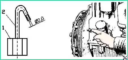
- Disconnect the high-pressure tube from the fitting of the first section of the pump and instead connect the control device (Fig. 3), which is a piece of high-pressure tube 100-120 mm long with a pressure nut at one end and the other end bent to the side by 150 -170°
- Fill the fuel pump with fuel, remove air from the low pressure system and create excess pressure with the manual priming pump until a continuous stream of fuel appears from the control device tube.
- Slowly rotating the diesel crankshaft clockwise and maintaining excess pressure in the pump head (booster pump), monitor the flow of fuel from the control device. When the fuel flow stops (up to 1 drop per 10 seconds is allowed), stop rotating the crankshaft.
- Unscrew the retainer from the threaded hole of the rear sheet (Fig. 3) and insert it with the reverse side into the same hole until it stops against the flywheel, while the retainer should coincide with the hole in the flywheel. This means that the piston of the first diesel cylinder is set to a position corresponding to (2-3) degrees before TDC for D-245.7E2 or (2.5-3.5) degrees before TDC for D-245.9E2.
If the latch does not match the hole in the flywheel, make the following adjustment:
- Remove the fuel pump drive gear hatch cover.
- Align the retainer with the hole in the flywheel by turning the crankshaft one way or the other.
- Loosen the fuel pump drive gear nut by (1.0...1.5) turns.
- Using a wrench, turn the fuel pump shaft counterclockwise by the nut until the pins stop against the edge of the groove of the fuel pump drive gear.
- Create excess pressure in the fuel pump head until a continuous stream of fuel appears from the control device tube.
- Turning the pump shaft clockwise and maintaining excess pressure, monitor the flow of fuel from the control device.
- When the fuel stops flowing, stop rotating the shaft and secure it by tightening the nuts securing the flange to the drive gear.
Re-check the timing of the start of fuel supply. Disconnect the control device and reinstall the high pressure pipe and manhole cover.
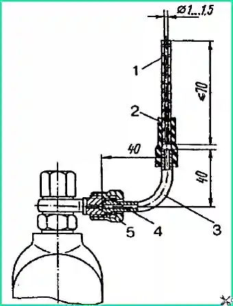
Momentoscope installation: 1 - glass tube; 2 - transition tube; 3 - tube from the high pressure fuel line; 4 - washer; 5 - cover nut
Check the setting angle of fuel injection advance of the PP4M10U1i injection pump in the following sequence:
- Set the regulator control lever to the position corresponding to the maximum fuel supply.
- Disconnect the high-pressure tube from the fitting of the first section of the injection pump and connect the torque scope instead (Fig. 4).
- Turn the diesel crankshaft clockwise with a wrench until the momentoscope of fuel appears from the glass tube without air bubbles.
- Remove some of the fuel from the glass tube by shaking it.
- Rotate the crankshaft in the opposite direction (counterclockwise) by (30-40)°.
- Slowly rotating the diesel crankshaft clockwise, monitor the fuel level in the tube as the fuel begins to rise
Stop rotating the crankshaft.
- Unscrew the retainer from the threaded hole of the rear sheet and insert it with the reverse side into the same hole until it stops in the flywheel, while the retainer should coincide with the hole in the flywheel. This means that the piston of the first diesel cylinder is set to a position corresponding to (3.5-4.5) degrees before TDC for D-245.7E2, or (4.5-5.5) degrees before TDC for D-245.9E2.
If the latch does not match the hole in the flywheel, make an adjustment by doing the following:
- Remove the hatch cover.
- Align the retainer with the hole in the flywheel by turning the crankshaft one way or the other.
- Loosen the fuel pump drive gear nut by (1.0...1.5) turns.
- Remove some of the fuel from the glass tube of the momentoscope, if there is any in it.
- Using a wrench, turn the special roller of the fuel pump by the nut in one direction or the other within the grooves located on the end surface of the fuel pump drive gear until the glass tube of the momentoscope is filled with fuel.
- Install the fuel pump shaft to its extreme (counterclockwise) position within the grooves.
- Remove some of the fuel from the glass tube.
- Slowly turn the fuel pump shaft clockwise until the fuel begins to rise in the glass tube.
- At the moment the fuel begins to rise in the glass tube, stop rotating the roller and tighten the gear fastening nuts.
- Check again when the fuel supply starts.
- Disconnect the torque scope and replace the high pressure pipe and manhole cover.
Checking injectors for injection start pressure and fuel atomization quality
Injectors are checked every 120,000 km. Remove the injectors from the diesel engine and check them on a stand.
The injector is considered to be in working order if it sprays fuel in the form of a mist from all five holes of the nozzle, without separately flying drops, continuous streams or thickenings.
The beginning and end of the injection must be clear, the appearance of drops on the tip of the nozzle is not allowed.
Check the spray quality at a frequency of (60-80) injections per minute.
If necessary, adjust the nozzles by changing the overall thickness of the shims.
Increasing the thickness of the washers (increasing spring compression) increases the injection pressure, decreasing it decreases it.
A change in the thickness of the washers by 0.1 mm leads to a change in the pressure at which the nozzle needle begins to rise by (1.3-1.5) MPa.
The number of adjusting washers should not exceed three pieces.
Injection start pressure for injectors: a) 455.1112010-50 – (24.5-25.7) MPa; a) 172.1112010-11.01 – (25.0-26.2) MPa.
When installing an injector on a diesel engine, tighten the injector mounting bolts evenly in (2-3) steps.
Final tightening torque (20-25) Nm.
Service the air filter through one maintenance service-2 or when the air filter clogged indicator sensor is triggered and the indicator lamp on the instrument panel lights up.
The alarm is triggered when there is a vacuum in the intake pipe (6-7) kPa ((600-700) mm water column).
Air filter maintenance involves purging the main filter element.
Contamination of the control filter element 6 indicates damage to the main filter element (break of the paper curtain, peeling of the bottoms).
In this case, it is necessary to blow out the control filter element, and replace the main one.
Service of the air filter must be performed in the following sequence:
- Remove the pan and the main filter element. It is not recommended to remove the control filter element from the housing.
- Blow off the main filter element with compressed air ear from the inside, and then from the outside until the dust is completely removed. To avoid breaking through the paper curtain, the air pressure should be no more than (0.2-0.3) MPa. The air stream should be directed at an angle to the surface of the filter element. During maintenance, it is necessary to protect the filter element from mechanical damage and oiling.
Attention! Do not blow the filter element with exhaust gases or wash it in diesel fuel.
- Clean the supply pipe, the internal surfaces of the housing and the air filter cover from dust and dirt.
- Install the filter element into the housing and, making sure that the o-rings are in the correct position, tighten the wing nut 2 by hand.
- Install the pallet in place.
Checking the tightness of the intake tract connections is carried out at each TO-2.
For testing, it is recommended to use the KI-4870 GOSNITI device.
If the device is missing, the tightness is checked visually.
Check the fastening of the hoses and, if necessary, tighten their clamps, especially the hoses connecting the air filter to the engine intake manifold.
Hoses must be pushed onto the pipes at least 30 mm. Eliminate non-density.
The turbocharger does not require any special maintenance during operation. Disassembly and repairs during operation are not allowed.
Reliable and durable operation of a turbocharger depends on compliance with the rules and frequency of maintenance of diesel lubrication and air cleaning systems, using the type of oil recommended by the manufacturer, monitoring the oil pressure in the lubrication system, replacing and cleaning oil and air filters.
Damaged oil supply and drain lines, as well as air lines connecting to the turbocharger, must be replaced immediately.
When replacing a turbocharger, fill the oil supply hole with clean engine oil up to the level of the flange, and when installing gaskets under the pipeline flanges, do not use sealants.
If a malfunction occurs, the compressor should be sent to a specialized workshop.