The bus body is a load-bearing all-metal welded structure, which consists of six pre-assembled units: base, left and right sidewalls, front part, rear part and roof
The base of the body (Fig. 1) consists of two longitudinal elements (spars) | - shaped section, interconnected by crossbars.
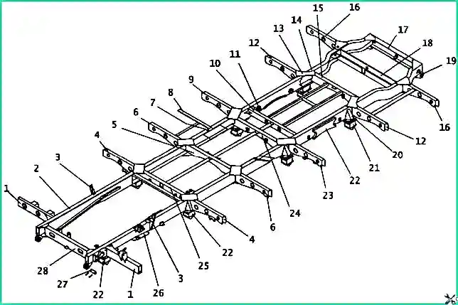
Body base: 1 - front console; 2 - front spar; 3 - shock absorber bracket; 4 - console No. 2; 5 - cross member No. 2; 6 - console No. 3; 7 - connecting insert for side members; 8 - tool box beam; 9 - console No. 4; 10 - shock absorber mounting beam; 11 - bushing for fastening the suspension spring axis; 12 - console No. 5; 13 - scarf; 14 - rear right spar; 15 - cross member No. 4; 16 - console No. 6; 17 - rear cross member; 18 - spare wheel beam; 19 - towing eye; 20 - amplifier; 21 - spring bracket superstructure; 22 - spring bumper amplifier; 23 - gas tank mounting console; 24 - cross member No. 3; 25 - cross member No. 1; 26 - spring buffer mounting plate; 27 - towing eye bolt; 28 - front beam
Consoles are welded to the outer walls of the side members for connection with the sidewall posts. To attach the spring brackets to the side members, special add-ons are welded.
Seat belts are designed to reduce the risk of injury to a person by limiting the movement of his body in the event of sudden bus braking or a collision.
Seat belts are installed on the driver’s seat, and also, upon customer’s request, on passenger seats, with the exception of seats in which the passenger is placed sideways in relation to the direction of travel of the bus.
Seat belts consist of straps with a locking buckle, an emergency-locking retractor and fasteners.
The buckle allows you to hold and quickly unfasten the belt.
The emergency locking retractor consists of a retractor and a locking mechanism.
The retractor automatically adjusts the length of the strap depending on the driver's body type and, under normal driving conditions, does not restrict the driver's freedom of movement. The locking mechanism limits the movement of the belt.
The mechanism is activated in the event of an accident due to the deceleration of the bus or a combination of the deceleration of the bus and the movement of the belt.
Using seat belts as intended
To fasten the belt, insert the tongue of the end of the strap into the lock until it clicks, without allowing the straps to twist. To unfasten the belt, you need to press the red lock button.
Belts do not require adjustment or maintenance.
It is recommended to periodically inspect the belts to detect any wear or damage of any kind.
If the straps become dirty, clean them with a mild soap solution.
Attention! Belts must be replaced with new ones if they have been subjected to critical load in a traffic accident or have abrasions, tears or other damage.
Passenger door is double-leaf.
The leading leaf is mounted on a lower ball joint, which provides the necessary adjustment of the height of the leaf position.
To guide the movement of the sash when closing and opening, there is a guide roller that moves along the chute.
The bus passenger door drive consists of a pneumatic control mechanism, air supply pipelines and a door pneumatic cylinder.
When the door mechanism operates, air enters from the pneumatic cylinder through the inlet fitting into the pneumatic distributor.
The pneumatic distributor controls air flows into the corresponding cavities of the pneumatic cylinder depending on electrical control signals from the driver’s workplace.
In this case, the pneumatic cylinder rod moves and, accordingly, the door opens or closes.
When the door is opened or in its closed position, microswitches mounted on the pneumatic cylinder respectively close or open the circuits of the open position indicator lamp and the landing area lighting.
If there is an obstacle in front of the door leaf when closing it, the anti-pinch device (PPD) should operate and send a control voltage pulse to open the door.
The doors are controlled using electrical switches located on the instrument panel.
When the door is open, the warning lamp on the instrument panel in the door control switch lights up.
In addition to the switches, there are two buttons on the instrument panel for emergency door opening: one in the passenger compartment on the right above the door, the other outside to the right of the door.
The bus may have a passenger control mechanism door manufactured by JSC Michurinsky Plant Progress or LLC Camozzi Pneumatics.
Production control mechanism of OJSC Michurinsky Plant Progress (Fig. 2).
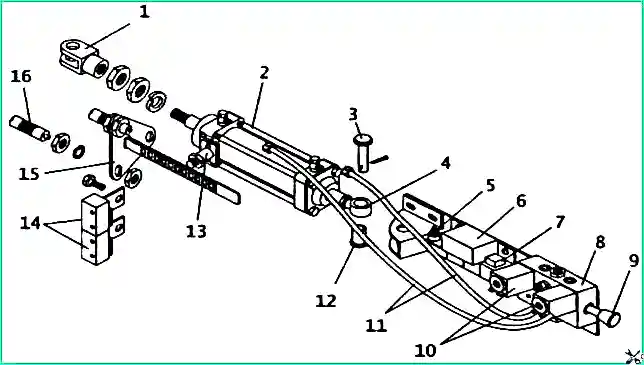
Pneumatic door drive (JSC Michurinsky Plant Progress): 1 - cylinder fork; 2 - cylinder; 3 - cylinder fastening pin; 4 - hinged bolt; 5 - resistor block; 6 - U33A electronic unit; 7 - diode assembly ; 8 - pneumatic distributor; 9 - emergency door opening button; 10 - electromagnet; 11 - hose; 12 - bolt sleeve; 13 - slot sensor; 14 - microswitch; 15 - stop bracket with rack; 16 - stop
The pneumatic drive is connected to the electrical control circuits of the bus using electrical connections according to the electrical diagram (Fig. 3).
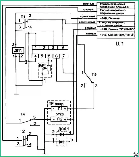
Possible malfunctions and ways to eliminate them
Commands to open (close) the door are not processed
- Contacts of electrical connections are broken
Check the reliability of the electrical contacts
- Pneumatic supply hose is crushed
Lay the air hose without kinks
- The filter is clogged
Replace the filter
- The diodes in the DSB1 diode assembly are faulty (broken)
Replace the diode assembly DSB1
No indication of door open or closed position
- Microswitches T1 do not work
Replace microswitches T1
- The position of the stop (controlling the microswitch) is not adjusted
Adjust the stop position
Landing area lighting missing
- Microswitch T2 does not work
Replace microswitches T2
- The position of the stop (controlling the microswitch) is not adjusted
Adjust the stop position
When a control pulse is applied to close the door, the door does not close
- Failure of electronic control unit UZZA
Replace the UZZA control unit
After giving a signal to close, the door does not close or, after making a small movement, opens
- Failure of one of the UZZA elements: slot sensor, electronic UZZA, resistor block
Alternate replacement of UZZA elements
After giving a signal to close, the door, having closed, opens spontaneously
- Failure of one of the UZZA elements: slot sensor, electronic UZZA, resistor block
Alternative replacement of UZZA elements, starting with the UZZA electronic unit and resistor block
- Microswitches T1 do not work
Replace microswitches T1
- The position of the stop (controlling the microswitch) is not adjusted
Adjust the stop position
Procedure for replacing the filter
A decrease in the speed of movement of the door leaf or its stop, caused by a possible decrease in the throughput (due to clogged pores) of the filter, can be eliminated by replacing the filter in the following sequence:
- Disconnect electrical and pneumatic power.
- Disconnect the inlet air hose by unscrewing the nut.
- Unscrew the inlet fitting from the pneumatic distributor.
- Remove the retaining ring, remove the filter and replace with a new one.
- Connect in reverse order.
Maintenance
When servicing the pneumatic door drive periodically (during maintenance-1), you should check the fastening of the pneumatic drive, its components and the connection of external circuits, and also remove dust and moisture from the parts of the pneumatic drive.
Passenger door control mechanism manufactured by Michurinsky Plant Progress OJSC or Camozzi Pneumatics LLC
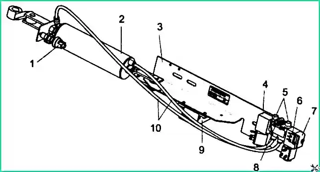
Pneumatic door drive (Camozzi Pneumatics LLC): 1 - limit switch (K1); 2 - pneumatic cylinder (PC); 3 - panel; 4 - electric pneumatic distributor (P3); 5 - throttle-muffler; 6 - microswitch (short circuit); 7 - emergency button (KN); 8 - entrance; 9 - control controller (CU); 10 - pipelines
The pneumatic drive is connected to the electrical control circuits of the bus using electrical connectors, according to the diagram in Fig. 5
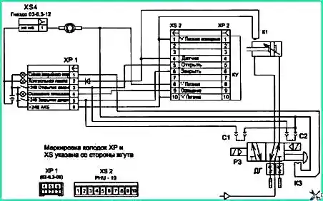
Electro-pneumatic diagram of a door drive manufactured by Camozzi Pneumatics LLC: KU - counter-clamp control controller; ХР1, ХР2 - pin block; XS2, XS3, XS4 - socket block; C1, C2 - pneumatic distributor solenoids; K3 - microswitch; K1 - sensor; DG - throttle-muffler
The anti-clamp control unit (CU) is designed to turn on the pneumatic distributor to open the doors in the event of a passenger being clamped, as well as turn on and off the landing area lighting lamp.
The block also generates a signal to the driver about unauthorized opening of the door.
The inputs of the unit receive signals from the limit switch (K1), which determines the closed position of the door leaf, and from the control button on the driver’s remote control.
If the input receives a command from the driver’s remote control “Open the door”, and then a signal that the door is open, then the control unit issues a command to turn on the landing light lamp and goes into standby mode for the “Close” signal from the driver remote control .
If the controller input receives a signal from the limit switch that the door is open, but the “Open the door” command was not received from the driver’s remote control, then the unit turns on the emergency opening buzzer, which sounds until the driver uses the remote control won't close the door.
When the “Close” command is received, a program timer is activated, set to the time during which the door must be guaranteed to close.
If during this time:
- - the door is closed (a signal is received from the limit switch), the platform lighting lamp turns off and the counter-clamp control unit goes into readiness mode for the next cycle.
- - the door has not closed (the signal from the limit switch K1 has not been received), then this is identified as the fact that the passenger is clamped, and the unit sends a signal to the pneumatic distributor coil (P1), moving it to the “door open” position.
The program of the counter-clamp control unit has a mode for automatically disabling the counter-clamping function.
The mode of automatic disabling of the anti-clamp function is activated if the door is opened without receiving the “Open” command from the driver’s remote control, namely when opening the door using the manual emergency opening button.
To restore the anti-clamp function, it is necessary to carry out a full normal cycle of opening and closing the door from the driver's remote control
If the “Close” button is pressed while the door is closed (for example, if the “Door Open” signal appears when the limit switch fails), the anti-clamp function is automatically disabled to prevent the doors from opening while moving. In addition, the anti-clamp function will be blocked as long as the “Close” button on the driver’s remote control is pressed.
Maintenance
Attention! Only specialists who know their design and operating rules are allowed to operate and maintain drives.
Installation, disconnection, and maintenance of drives should be carried out with the pneumatic and electrical power supply turned off.
Drive installation procedure
- Install the drive in its original place, orienting the mounting bolts approximately in the center of the grooves on the drive panel. Lock the drive.
- Push the rod into the cylinder until it stops.
- Close the bus door all the way.
- Connect the fork of the pneumatic cylinder rod with the door swing post lever, making sure that the rod is extended at least 2-3 mm from the cylinder compared to its original position. Otherwise, move the drive panel along the grooves of the fasteners to the right by 2-3 mm.
- Adjust the position of the limit switch relative to the pressure stop and secure it with lock nuts.
- Connect the “Input” fitting to the bus pneumatic system. Connect the electrical circuit blocks of the drive (see Fig. 4 and 5) with the mating blocks of the bus.
Preparing the drive for operation
- Apply pneumatic and electrical power to the actuator.
- Check operation by opening and closing the door from the driver's seat.
- Adjust the speed of opening and closing doors using throttles-mufflers located on the pneumatic distributor. (Initial settings of the throttle-mufflers are made when the drive is assembled at the manufacturer).
Keep in mind that the threads on the throttle head are left-handed, so turning the throttle head clockwise (to the right) reduces the door speed, and turning it counterclockwise (to the left) increases the door speed.
- Check the operation of the emergency door opening button by pressing it.
To then close the door, you must press the “Close” button on the driver’s remote control.
Attention! Manually returning the emergency button does not allow you to close the door.
- I will adjust adjust the position of the limit switch (K1) so that when the door is closed, the “Door open” indication does not light up on the driver’s console, and the gap between the stop bar on the cylinder rod and the limit switch body is at least 2 mm.
- Configure the counter-clamp control unit (CU). The anti-clamp control unit is an intelligent module that allows you to set the anti-clamp response time depending on the closing speed of a particular door in the range from 1 to 8 seconds. Factory setting is 3 seconds.
To set up the anti-clamp block, you must do the following:
6.1. Turn on side lights.
6.2. On the driver's remote control, press the "Open door" button (the door will open) and hold it pressed (at least 30 seconds) until the door light lamp begins to flash, which means the unit enters programming mode.
6.3. Press the “Close” button on the driver’s remote control (the door should close, and the controller will remember the real time it was closed).
Attention! The anti-clamp control unit must be adjusted after each door adjustment, in accordance with the above-described point of adjusting the speed of opening and closing the door using throttles-mufflers.
Check before starting work (during operation)
Check the drive before starting work in the following sequence:
- Check the operation of the doors by opening and closing them from the driver's seat.
- Check that the “Door Open” alarm is triggered.
- Check by ear for air leaks with the door open and closed.
- Check the emergency door opening mechanism when the vehicle is parked by pressing the emergency opening button. To return the emergency button, press the “Close Door” button on the driver’s remote control.
- Check the operation of the anti-clamping mechanism by opening the door, then closing it, and while closing it, hold the door shut.
When servicing the pneumatic door drive periodically (during maintenance-1), you should check the fastening of the pneumatic drive, its components and the connection of external circuits, and also remove dust and moisture from the parts of the pneumatic drive.
Possible malfunctions and ways to eliminate them
The door does not open (does not close)
- Pneumatic hose is crushed
Release the air hose
- Broken electrical wiring
Remove break
- Air leak from the pneumatic system
Fix leak
Slow door movement
- The adjustment of the throttle-mufflers (DH)
Adjust chokes-mufflers
- The filters of the choke-mufflers (DG) are dirty
Remove the mufflers and blow them with compressed air
Replace chokes-mufflers
The counter-clamp is activated when there is no obstacle
- No power supply to the drive
Restore power
- Response time set too long
Configure the anti-clamp control unit
- The counter-clamp control unit is in programming mode
End programming cycle
- Limit switch position misaligned
Adjust the position of the limit switch
Bus windows
The wind windows of the bus are made of safety three-layer polished glass.
The rear window consists of two tempered polished glasses connected by a profile. The side windows are made of tempered flat polished glass.
The first and last windows on the left side are emergency ones with pull-out cords, in addition, the rear window in an emergency is easily broken with a hammer located on the right inner rear panel.
The rear view mirrors are fixed in the desired position using springs and a comb lock.
A place for a fire extinguisher is provided on the driver's bulkhead pillar.
A place for a first aid kit is provided on the front panel to the right of the instrument panel.
The sun blind is fixed inside the passenger compartment above the left windshield and serves to protect the driver’s eyes from direct sunlight.
The curtain is lowered manually. The curtain is raised automatically by pressing down on the cord located on the left side of the curtain.
Body ventilation is carried out through side windows and ventilation hatches.
For ventilation of the driver's cabin, there are hatches above the windshield and in the left corner panel of the front panel, which can be covered with covers and a flap from the driver's seat.
All ventilation hatches work to pump fresh air into the body while the bus is moving.
The second ventilation hatch is also an emergency exit. When you turn the emergency drive handle, the hatch cover is disconnected from the body and thrown outward by hand, freeing up the emergency exit.
Interior heating is carried out using heaters connected to the systemse engine cooling.
The interior heater consists of a heat exchanger and a fan.
The air forced by the heater fan, passing through the radiator, heats up and warms the interior.
Heaters have two operating modes - full and partial.
They are controlled using two-position keys located on the instrument panel.
One switch controls the heaters located on the right side of the cabin, the other controls the heaters on the left side of the cabin.
The windshield windows are blown with warm air heated by a separate heater.
The heater control switch is located on the instrument panel.
For effective heating of the interior and blowing of windshields, it is necessary to maintain a sufficiently high temperature of the coolant in the engine cooling system and ensure circulation of the liquid through the pipelines, which is achieved by operating a liquid heater and circulation pump, which must be constantly on.
Towing device
To tow the bus, use towing lugs, which are located on the front and rear side members of the base.
Places for installing jacks
For the purpose of lifting the body, the bus has four special points for installing a jack, located behind the arches of the front and rear wheels.
Body maintenance
Inspect the body regularly during daily maintenance. Repair if cracks appear.
If the surface of the body is contaminated with oil, remove it with a soft cloth moistened with gasoline, followed by wiping it dry.
To maintain the cleanliness and gloss of all polished and anodized aluminum parts of the body and instrument panel, do the following: wipe the surfaces of these parts daily with a clean soft cloth; and during maintenance, use a cloth soaked in polishing water, followed by wiping dry.
Wash the seat upholstery with water or soapy water using a soft hair brush and wipe with a dry cloth.


