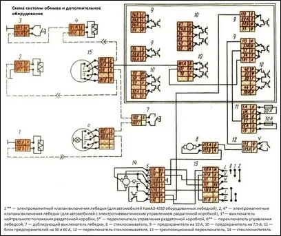
The washing system consists of a washer and switch 12 connected in a single-wire circuit (see Fig. 1.)
The electrical circuit is protected by a PR310 type fuse.
Additional electrical equipment for KamAZ vehicles
The electrical equipment diagrams of KamAZ-5320 and KamAZ-55102 vehicles differ in the presence of additional electrical equipment for the platform lifting mechanism on the KamAZ-55102 dump truck:
- -two solenoid valves for raising and lowering the platform;
- - hydraulic distributor solenoid valve; power take-off solenoid valve;
- - hydraulic distributor switch; platform lift switch.
Unlike the KamAZ-55102 car, the KamAZ-5511 car does not have:
- - road train identification lights and their switch;
- - trailer socket;
electro-pneumatic valve and pneumatic sound signal; solenoid valve of the hydraulic system distributor and its switch.
On truck tractors, in comparison with the KamAZ-5320 flatbed vehicle, an additional cover for lighting the bed and a headlight for lighting the fifth wheel are installed.
On KamAZ-4310 vehicles, an alternating current generator G288 with a rated power of 1000 W is used.
The voltage generated by this generator is automatically maintained by a separate voltage regulator (type 1112.3702).
In addition, on off-road vehicles with a transfer case and a winch in their transmission, an additional electrical system is provided for shifting gears in the transfer case and turning on the power take-off.
Solenoid valves 2 and 4, which control the shift mechanism in the transfer case, are activated by the three-position switch 5 and the neutral position switch 3.
The electrical connection is made in a single-wire circuit, with the exception of solenoid valve 4, the negative terminal of which is connected to ground through the neutral position switch of the transfer case.
Solenoid valve 1, which controls the power take-off mechanism, is activated by a three-position switch 6.
The electrical connection is made in a single-wire circuit.
The electrical circuits of the gear shifting systems in the transfer case and the control of the winch drive are protected by a fuse type 13.3722.


