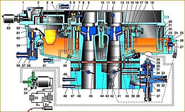
Elements of the K-151 carburetor
The K-151D carburetor, installed on a car with a ZMZ-4063 engine, has two adjacent vertical channels (chambers) for air passage, in the lower part of each of which a rotary throttle valve is installed
The throttle valve drive is designed so that as you press the accelerator pedal, first one and then the other valve opens.
The chamber in which the throttle valve opens earlier is called the first, the other is called the second.
In the middle part of each of the main air channels there are cone-shaped constrictions - diffusers, which create a vacuum in the air flow necessary for sucking fuel from a special container located in the carburetor body - the float chamber.
The fuel level in the float chamber necessary for normal operation of the carburetor is maintained using a mechanism with a float and a needle valve.
The carburetor float mechanism is completely located (together with the needle and float) in the carburetor body and is accessible for visual inspection after removing the cover (the fuel level in the float chamber can be measured without removing the float).
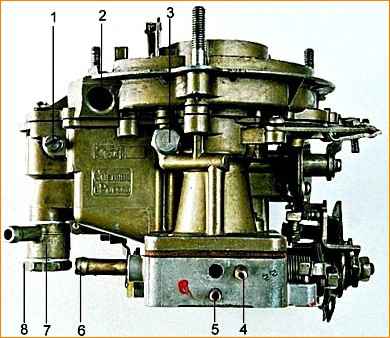
The carburetor consists of three main parts: the upper body cover, with a flange and studs for fastening the air filter housing, with a float chamber ventilation device and starting device parts.
The cover is attached with seven screws to the carburetor body through a cardboard gasket;
- middle - carburetor body, with a float chamber and float mechanism, fuel supply fitting and fuel metering systems;
- bottom - throttle body, with throttle valves and their drive mechanism, as well as an idle device attached to the carburetor body from below with two screws through three gaskets (two thin - cardboard and one thick - plastic).
The carburetor contains the following systems, devices and mechanisms:
- - float mechanism;
- - fuel metering systems;
- - main dosing systems of the first and second chambers;
- - idle system;
- - transition system of the second chamber;
- - econostat;
- - accelerator pump;
- - starting device;
- - economizer valve for shutting off fuel supply in forced idling mode (EFI);
- - crankcase ventilation system;
- - float chamber ventilation system; throttle valve control mechanism
The idle system is autonomous, with adjustment of the mixture composition.
In the second chamber of the carburetor there is a transition system with fuel supply directly from the float chamber, which comes into operation when the throttle valve of the second chamber is opened.
A diaphragm-type accelerator pump that comes into operation when you sharply press the accelerator pedal.
To enrich the combustible mixture at full load, an econostat is provided in the second chamber.
The starting device is a semi-automatic type, consisting of a pneumatic corrector, a system of levers and an air damper, which is closed before starting a cold engine using a manual drive.
At the moment of starting the engine, the pneumatic corrector, under the influence of vacuum arising in the intake manifold, automatically opens the air damper to the required angle, ensuring stable operation of the engine when warming up.
The fuel supply cut-off system (forced idle economizer) comes into operation in the forced idle mode when Engine braking of a vehicle when there is no need to supply fuel to the engine.
This ensures fuel savings and reduces the emission of toxic substances into the atmosphere.
Rinsing and cleaning the carburetor
Flushing the carburetor, unlike washing other units, is as important a means of maintaining carburetor performance as adjustment.
The principle of operation of the carburetor, based on the movement of fuel and air in narrow channels, determines the need to constantly maintain cleanliness both inside and outside.
Oily deposits on the outer surface of the carburetor do not have any effect on its operation since they cannot get inside, but a thick layer of dirt on the lever mechanism can impair the mobility of the levers and rods.
In this case, and also before disassembling the carburetor, even partially, its outer surface must be washed.
But remember that with every wash, even the most thorough one, an additional amount of abrasive and sand gets into the worn-in rubbing pairs of the lever mechanism, so we do not recommend washing the carburetor too often. For the same reasons, it is better not to lubricate the lever mechanism.
For external carburetor cleaning, you can use unleaded gasoline, kerosene or diesel fuel.
For reasons of fire safety, it is preferable, however, to use special detergents in aerosol packaging, which are washed off with water along with dirt.
After washing, blow off the surface of the carburetor with compressed air.
The internal cavities of an undisassembled carburetor must not be blown out with a strong stream of compressed air, as the float mechanism may be damaged.
Wash the internal surfaces and parts with the same liquids as the external ones.
But since gasoline and kerosene do not dissolve varnish deposits in air channels and jets well, it is more effective to use solvents of grades 646-649, acetone, dichloroethane, amyl acetate and various alcohols.
Do not wash an unassembled carburetor with solvents, acetone, dichloroethane, etc.
If accidentally ingested, they dissolve the polymer and rubber materials from which some gaskets and diaphragms are made, and the carburetor fails.
For the same reason, when washing a disassembled carburetor, remove these parts and wash them separately only in gasoline.
Recently, so-called “Carburetor Cleaners” in aerosol packages have become widespread.
These highly effective compounds containing a complex of potent solvents and detergent additives, according to the instructions, are to be injected directly into the carburetor by removing the air filter cover.
They almost instantly dissolve dense varnish-like contaminants in air channels and jets.
But use them very carefully and only in cases where you urgently need to start an engine that has stopped due to excessive contamination of the carburetor.
If there is an excessive accumulation of contaminants in the carburetor and a large portion of the cleaner, the contaminants loosen and instantly clog all air and fuel channels; as a result, a satisfactory working carburetor will require complete disassembly for thorough washing.
In addition, in a carburetor that has been operating for a long time, leaks in the connectors that have arisen over time are gradually clogged with dust particles, which in this case play the role of an additional seal.
The cleaner will wash out these particles, and normal operation of the carburetor without replacing gaskets and seals will be impossible.
For this reason, it is better to use this highly effective product for flushing a disassembled carburetor.
Always strictly follow one of the main rules for flushing the carburetor - never wipe the washed parts, especially the jets, even with a completely clean rag.
Even an inconspicuous lint, if, for example, it gets into the fuel nozzle of the idle system, it will completely stop the fuel supply and stop the engine.
After washing, dry parts only by blowing them with a strong stream of compressed air.
For the same reason, do not remove sediment on the bottom of the float chamber with a rag. It, along with gasoline, must be carefully pumped out with a rubber bulb.
If the first attempt failed to remove all the sediment, add clean gasoline to the float chamber and repeat the operation until the bottom of the chamber is completely clean.
")

")
")
")
")
")
")
")