The control unit has a self-diagnosis mode, which can be used to determine faults in the system.
If the control unit in self-diagnosis mode cannot determine the malfunction, then you should use the special DST-2 device. In this case, you must follow the instructions supplied with the device
The control unit, in self-diagnosis mode, issues light codes to the warning lamp in the instrument cluster.
Each malfunction is assigned its own digital code. It is determined by the number of times the lamp is turned on.
First, count the number of times the lamp is turned on to determine the first digit of the code (for example, number 1 – one short switch on for 0.5 seconds, number 2 – two short switches).
Then there is a pause of 1.5 s. After it, the number of activations is counted to determine the second digit of the code, then the third, after which there is a pause of 4 seconds, which determines the end of the code.
If the code is three-digit, then the duration of the first digit is 1 second.
- Turn on the ignition. The warning lamp should light up for 0.5 seconds and go out if the self-diagnosis system does not detect a malfunction.
In this way, the serviceability of the signal lamp itself is determined.
- If a malfunction is detected in the system, the lamp may remain on continuously or only when the engine is running. In any case, it is necessary to diagnose and maintain the engine management system.
- Turn off the ignition
- To switch the control unit to self-diagnosis mode
- - disconnect the battery for 10-15 seconds and connect again;
- - start the engine and let it idle;
- - open the cover of the diagnostic connector and connect pins “10” and “12” of the connector with a separate wire according to Fig. 1
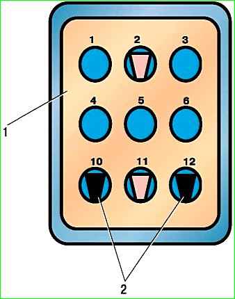
The connector is installed in the engine compartment on the front panel on the right side.
- After the control unit is switched to self-diagnosis mode, the warning lamp should flash code 12 three times, which indicates the start of the self-diagnosis mode.
The following codes will indicate an existing fault or several faults.
Each code is repeated three times.
After all the existing fault codes are displayed, code 12 is displayed three times and the codes are displayed again.
If the control unit cannot detect a malfunction or there are no malfunctions, then code 12 is displayed.
The main fault codes are shown in the table
Memorized fault codes can be cleared by disconnecting the battery ground terminal for more than 10 seconds.
It is necessary to ensure that the ignition is turned off to avoid damage to the electronic unit.
In addition, code 62 - RAM error - will be stored in the list of one-time faults for some time
It is necessary to take into account that when the battery is disconnected, the information accumulated in the RAM about the state of the engine is erased and the engine may not work satisfactorily upon first start
To adapt the control system, start the engine, let it idle for at least 1 minute, then warm up the engine to operating temperature and drive the vehicle for at least 1 km in partial load mode.
Fault codes for the ZMZ-406 microprocessor ignition system with the Mikas 5.4 control unit
- 12 Diagnostic circuit performance
- 21 Low signal level of the coolant temperature sensor
- 22 High signal level of the coolant temperature sensor
- 25 Low voltage level of the vehicle's on-board network
- 26 High voltage level of the vehicle's on-board network
- 51 Control unit malfunction
- 53 Synchronization sensor malfunction
- 61 Unauthorized restart of the control unit
- 62 Loss of information in the control unit RAM
- 63 ROM failure
- 64 Malfunction when reading non-volatile memory of the control unit
- 65 Malfunction when writing to the non-volatile memory of the control unit
- 182 Diagnostic lamp circuit malfunction (open)
Fault codes for the ZMZ-40522 microprocessor ignition system with the Mikas 7.1 control unit
- 13 Low signal level of the mass air flow sensor
- 14 High signal level of the mass air flow sensor
- 15 Low signal level of the absolute pressure sensor
- 16 High signal level of the absolute pressure sensor
- 17 Low signal level of temperature sensor input air
- 18 High signal level of incoming air temperature sensor
- 21 Low signal level of the coolant temperature sensor
- 22 High signal level of the coolant temperature sensor
- 23 Low signal level of the throttle position sensor
- 24 Throttle position sensor signal high
- 25 Low voltage level of the on-board network
- 26 High level of on-board network voltage
- 27 Malfunction of the crankshaft position sensor (synchronization)
- 28 Same
- 29 >>
- 31 Low signal level of the first CO corrector
- 32 High signal level of the first CO corrector
- 33 Low signal level of the second CO corrector
- 34 High signal level of the second CO corrector
- 35 Low signal level of the first oxygen concentration sensor
- 36 High signal level of the first oxygen concentration sensor
- 37 Low signal level of the second oxygen concentration sensor
- 38 High signal level of the second oxygen concentration sensor
- 41 First knock sensor circuit malfunction
- 42 Second knock sensor circuit malfunction
- 43 Exhaust gas recirculation valve signal low
- 44 Exhaust gas recirculation valve signal high
- 45 Low signal level of the canister purge valve
- 46 High signal level of the canister purge valve
- 47 Low power steering signal
- 48 Power steering signal high
- 51 Control unit 1 malfunction
- 52 Control unit 2 malfunction
- 53 Malfunction of the crankshaft position sensor (synchronization)
- 54 Malfunction of the camshaft position sensor (phase)
- 55 Vehicle speed sensor malfunction
- 61 Unauthorized restart of the control unit
- 62 Control unit RAM fault
- 63 Control unit ROM malfunction
- 64 Failure to read non-volatile memory of the ECU
- 65 Failure to write non-volatile memory of the ECU
- 66 Malfunction when reading the identification code of the control unit
- 67 Immobilizer error
- 68 Same
- 69 >>
- 71 Low idle speed
- 72 High idle speed
- 73 Rich mixture when adjusted by the first oxygen concentration sensor
- 74 Lean mixture when adjusted using the first oxygen concentration sensor
- 75 Rich mixture when adjusted by the second oxygen concentration sensor
- 76 Lean mixture when adjusted using the second oxygen concentration sensor
- 79 Malfunction when controlling EGR by SEGR
- 81-84 Maximum offset of the ignition timing of the knock adjustment in cylinders 1-4
- 91-94 Malfunction in ignition circuit 1-4 (short circuit)
- 99 High voltage driver fault
- 131 Injector 1 fault (short circuit)
- 132 Injector 1 malfunction (break)
- 133 Injector 1 fault (short circuit to ground)
- 134 Injector 2 fault (short circuit)
- 135 Injector 2 malfunction (break)
- 136 Injector 2 fault (short circuit to ground)
- 137 Injector 3 fault (short circuit)
- 138 Injector 3 malfunction (break)
- 139 Injector 3 fault (short circuit to ground)
- 141 Injector 4 fault (short circuit)
- 142 Faulty injector 4 (break)
- 143 Faulty injector 4 (short circuit to ground)
- 167 Fuel pump relay circuit malfunction (short circuit)
- 168 Malfunction u1094 of the fuel pump relay circuit (open)
- 169 Fuel pump relay circuit malfunction (short circuit to ground)
- 171 Recirculation valve circuit malfunction (short circuit)
- 172 Recirculation valve circuit malfunction (open)
- 173 Recirculation valve circuit malfunction (short circuit)
- 174 Canister purge valve circuit malfunction (short circuit)
- 175 Canister purge valve circuit malfunction (open)
- 176 Canister purge valve circuit malfunction (short circuit to ground)
- 177 Main relay circuit malfunction (short circuit)
- 178 Main relay circuit malfunction (open)
- 179 Main relay circuit malfunction (short circuit to ground)
- 181 Diagnostic lamp circuit malfunction (short circuit)
- 182 Diagnostic lamp circuit malfunction (open)
- 183 Diagnostic lamp circuit malfunction (short circuit to ground)
- 184 Tachometer circuit malfunction (short circuit)
- 185 Circuit failure achometer (break)
- 186 Tachometer circuit malfunction (short circuit to ground)
- 191 A/C relay circuit malfunction (short circuit)
- 192 A/C relay circuit malfunction (open)
- 193 A/C relay circuit failure (short to ground)
- 194 Cooling fan relay circuit malfunction (short circuit)
- 195 Cooling fan relay circuit malfunction (open)
- 196 Cooling fan relay circuit malfunction (short to ground)
- 231-234 Malfunction in ignition circuit 1-4 (open)
- 241-244 Malfunction in ignition circuit 1-4 (short circuit to ground)
- 251 Malfunction of the mass air flow sensor burning circuit (short circuit)
- 252 Malfunction of the mass air flow sensor burning circuit (open)
- 253 Malfunction of the burning circuit of the mass air flow sensor (short circuit to ground)
")

")
")
")
")
")
")
")