Cylinder liners are “wet” type, made of special wear-resistant cast iron
To ensure running-in and protection against corrosion, a special wear-resistant phosphate coating is applied to the liners.
The liners are installed with their seating belts into the bores of the cylinder block and pressed against it with the head through the collar and gasket
The height of the cylinder liner collar is 9.6 mm. A layer of Lactite-5900 sealant is applied to the lower end of the block bore under the cylinder liner.
The protrusion of the liner flange above the surface of the cylinder block should be within: 1.6+0.035-0.057 mm.
On the outer surface of the liner in the lower part there are grooves for anti-cavitation and sealing rings to protect against cavitation and coolant getting into the oil sump.
The sleeves are not divided into size groups based on the internal diameter. The designation of the manufacturer and the technical control mark are applied to the upper end of the sleeve.
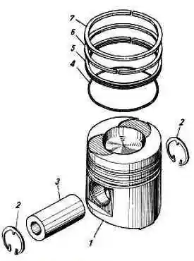
Pistons are cast from a special aluminum alloy. On the side surface there are three grooves for piston rings - (two for compression rings and one for the oil scraper ring).
The groove for the upper compression ring is protected from wear by an insert made of special cast iron.
To ensure the performance of the working process, the combustion chamber has an undercut on the side surface and a displacer on the bottom. There are recesses on the bottom for the gas distribution valves.
The height from the bottom to the axis of the hole for the piston pin is 85 mm. The diameter of the finger hole is 52 mm. The piston is cooled with oil from a fixed nozzle.
For YaMZ-6583.10 engines with individual heads, pistons 658.1004015 with a central combustion chamber are installed.
Pistons are not divided into size groups based on their outer diameter.
The trademark of the manufacturer, product designation and material grade are applied to the inner surface of the piston; on the bottom there is a sign of technical control.
Piston rings are made of special cast iron, split, and have a wear-resistant coating on the working surface. The rings are installed in the piston grooves.
The “Top” marking should face the piston bottom, and the locks of adjacent rings should be rotated 180˚ relative to each other.
A set of rings 658.1004002 is installed on the piston, consisting of:
- - The upper compression ring has a double-sided trapezoid in cross-section with a barrel-shaped working surface with a chrome-ceramic coating shifted downward. Ring designation: 658.1004030.
- - Second compression ring of rectangular cross-section with a groove at the lower end on the inside. The work surface is chrome plated. Ring designation: 7511.1004032-01.
- - Oil scraper ring 4 mm high, box-type, with a twisted ground expander and chrome-plated working belts. Ring designation: 658.1004034.
On the upper end of the ring are the designation of the manufacturer and the word “Top” for compression rings.
Piston pin – hollow, floating type, nitrided to ensure wear resistance.
The pin is installed in the holes in the piston bosses, its axial movement is limited by spring thrust rings.
Crankcase ventilation system is a closed type with suction into the air intake system in front of the TCR, with an oil separator and a pressure control valve.
This system is environmentally friendly, as it eliminates harmful emissions of crankcase gases and oil mist into the atmosphere. In this case, the engine has only one exhaust system left.
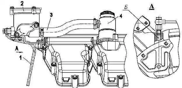
The crankcase ventilation system (Fig. 2) includes an oil separator 2, which is installed on the engine on a special bracket and connected to the breather with a supply hose 3, as well as oil drain pipes 1.
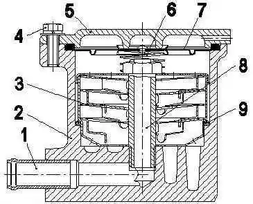
Crankcase gases from under the cylinder head cover through the breather and supply hose enter the oil separator pipe and then into the lower part of the glass, in which a package consisting of four disks 3 is located (Fig. 3).
Then the gases rise up to the diaphragm valve 7, which controls the pressure in the crankcase, are separated from the oil and are sucked through the outlet pipe 1 into the engine intake circuit.
Oil particles deposited on the disks flow into the lower part of the oil separator housing and are drained through a tube into the engine sump through a hydraulic seal, which is a cavity formed by ribs in the cylinder block and flywheel housing, filled with oil.
Before starting a new or repaired engine, fill the cavity with 20 cm of 3 engine oil used in the engine.
Emergency stop valve is designed for emergency shutdown of the engine in order to protect it from runaway, operation without oil, and other emergency situations that can lead to premature exhaustion of the engine life and its failure.
The emergency stop damper is controlled by:
- - automatic, from the electronic control unit;
- - remote, button on the instrument panel in the driver’s cabin;
- - manual, button on the housing 10 of the damper drive.
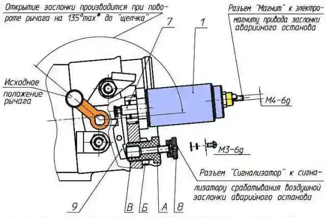
The damper (Figures 4, 5, 6) consists of two units: the intake pipe with the damper assembly 2 and the housing 10 with the emergency stop damper drive.

The damper is a round plate 11 mounted on an axis 3 installed in the holes located in the inlet pipe.
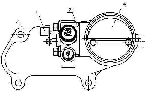
The closed position of the damper is ensured by the preload of spring 5 and the action of the air flow, since the damper is mounted on the axis with a transverse displacement.
Opening the damper to its original (open) position, including after it has been activated, is done by turning lever 4 135˚ clockwise with a force of 80-100 N (8-10 kgf) at the end of the lever until it “clicks.”
In this case, using the tooth of the damper axis and the protrusion of the latch, the damper is locked, and the cocking lever 4 must return to its original position under the action of spring 5.
The mechanism for driving the damper cocking lever from the driver's cabin to the chassis (its kinematics) should not interfere with this.
The cocking lever is not permanently connected to the damper axis.
When a 24V voltage is applied to the winding of electromagnetic drive 1 briefly for 1-2 s, the electromagnet armature is retracted, compressing its spring, and moves the latch 9, releasing the damper axis.
The damper, under the action of spring 5 and the air flow, turns in 0.1 s and blocks the air flow.
It is especially necessary to pay attention to the fact that the damper drive uses an electromagnet of the RS-336-02 type with a rated supply voltage of 12V.
To ensure reliable closing of the damper, 24V voltage should be supplied briefly, for 1-2 seconds no more.
To provide a short-term impulse, the signal from the instrument panel in the driver’s cabin should be carried out not by a toggle switch, but by a short-term power button.
Structurally, this button must be protected from accidental pressing and activation.
For emergency engine stop when the driver is outside the cab, there is a button 8 for manually closing the damper.
At the same time, the button functions as an emergency stop damper position sensor.
When the damper is closed, there must be contact between the button pusher and the damper latch, which should be indicated by a light bulb (LED) on the instrument panel in the driver's cabin.
If adjustments are necessary, do the following:
- - the damper must be in the closed position;
- - tighten the button screw until it touches the button pusher pin to the lock, as evidenced by the illuminated light bulb (LED) on the instrument panel in the driver's cabin and tighten the screw ¼ turn;
- - holding the screw in this position, tighten the lock nut.
If repairs are necessary, remove and install the damper on the engine in the “closed” position.
The layout (installation) of the engine on the car must provide easy access to the button for manually turning on the throttle and at the same time protection from accidental pressing.
It is prohibited to use the throttle for normal engine shutdown.
Fine fuel filter (Fig. 7) consists of a cap 4 with a rod 3 welded to it, a cover 6 and a filter element 5.
Drain plug 1 is screwed into the rod from below.
The seal between the cap and the lid is ensured by rubber O-ring 11.
The cap and the lid are connected by a bolt 7, under the head of which a sealing washer 8 is placed.
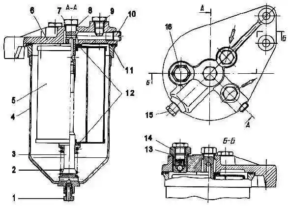
The replaceable filter element is made of special paper. Spring 2 presses the filter element to the cover.
The filter element is sealed at the end surfaces with 12 gaskets attached to the element.
A nozzle valve 14 with a plug 16 is screwed into the lid, which is sealed with a gasket 13.
Through the jet valve, part of the fuel is drained along with the air that has entered the low pressure system. The jet valve is adjusted to an opening pressure of 20-40 kPa (0.2-0.4 kgf/cm 2).
At low pressure in the system, which can be observed when starting the engine, the valve closes the channel and fuel does not drain, the fuel supply to the ECU is improved.
During operation, periodic drainage of sludge, replacement of the filter element, and also washing of the hood are provided.
On engines, use a replaceable fuel filter element 840.1117039 (030)-01 (T6307) manufactured by JSC DIFA, Republic of Belarus or Trading House Autofilter DIFA, Moscow, which has a Certificate of Conformity issued by the relevant certification center and manufactured during the period of validity of the permit for use issued by JSC Avtodizel.
Fan drive with friction clutch
The engines are equipped with a fan drive with a friction clutch, operating in both automatic and manual modes.
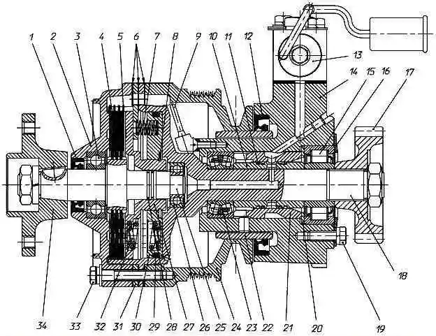
Fan drive: 1 - cuff; 2 - cover; 3 - bearing; 4 - driven disk; 5 - drive disk; 6 - gasket; 7 - release spring; 8 - thrust ring; 9 - scoop tube; 10 - spacer sleeve; 11 - sealing ring; 12 - cuff; 13 - solenoid valve; 14 - body; 15 - bearing; 16 - thrust flange; 17 - gear; 18 - drive shaft; 19 - bolt; 20 - washer; 21 - spacer sleeve; 22 - bushing; 23 - bearing; 24 - pulley; 25 - driven shaft; 26 - bearing; 27 - pressure clip; 28 - sealing ring; 29 - sealing ring; 30 - piston; 31 - piston stop; 32 - pressure spring; 33 - bolt; 34 - hub
The fan is off when the engine is not running.
After starting the engine, the fan impeller can rotate due to friction in the bearings and other mating parts of the disk clutch with a frequency of 200-500 rpm.
When the engine temperature condition is close to the highest optimal (+85˚ ... +93˚ C), oil from the switch under pressure enters fitting 13 (Fig. 8) of housing 14.
Next, through the hole in the housing, the radial holes in the bushings 10 and 22 enter the axial hole of the drive shaft 18, and from there to the piston 30.
The piston begins to move, transmitting forces through springs 32 to the holder, which presses on disks 4 and 5, selecting the gaps between them.
After compression of the drive and driven disks, the driven shaft 25 with the impeller begins to rotate at operating frequency.
After the engine temperature reaches a value close to the lowest optimum, the switch stops the oil supply.
The oil located under the piston 30, under the action of centrifugal forces, as well as springs 7, 32, moves through drainage holes through special channels into the internal cavity of the front cover 2 and pulley 24.
Using the scoop tube 9 and then through the channels in the housing, the oil enters the engine crankcase.
As the cavity under the piston 30 is freed from oil, it moves under the action of springs 7, 32.
The friction drive disks move apart and the fan turns off.
The fan drive is equipped with a KEM 32-23M solenoid valve, which is structurally similar to the KEM 32-23 valve, in order to increase its efficiency in preventing clogging, a permanent magnet is placed in the valve body to capture metal particles.
During operation, maintenance of the solenoid valve is not required; if necessary, the magnet can be cleaned of metal particles.
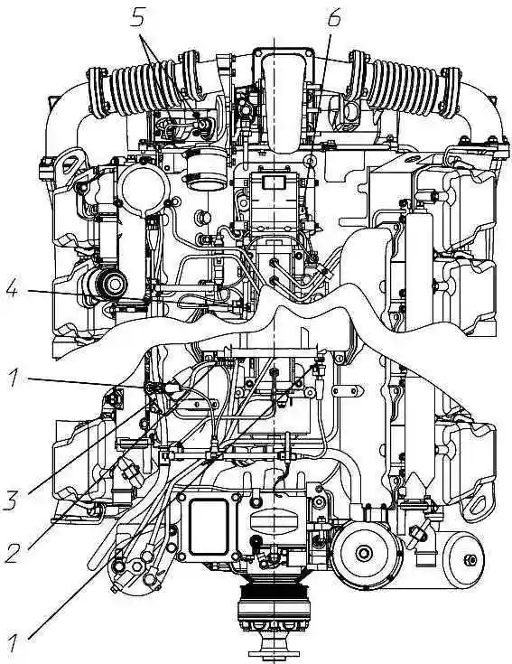
Location of sensors on the engine: 1 - temperature sensor 233.3828; 2 - air supply tube to the charge air pressure sensor; 3 - charge air pressure sensor 23.3855; 4 - fuel temperature sensor 192.3828; 5 – synchronization sensor DS-1406.3847060-01; 6 – actuator position sensor 36.3855-20
The location of the sensors on the engine is shown in Fig. 9.