Remove the cylinder head
Remove the crankcase and crankcase gasket
Remove the oil pump.
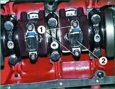
Remove the nuts 1 of the connecting rod bolts and remove the cap 2 of the connecting rod.
Since the lid sits tightly, knock it down with gentle hammer blows.
Remove the connecting rod bearing shell from the cover.
Push the piston into the cylinder so that it comes out of the cylinder, and then remove it along with the connecting rod.
Remove the connecting rod bearing shell from the connecting rod.
Remove the piston with the connecting rod from the cylinder carefully so as not to damage the cylinder mirror.
Check the marks on the connecting rod and connecting rod cap.
If the marks are not visible, mark the connecting rod and cap with the cylinder number.
- In the same way, remove the remaining pistons with connecting rods.
- Remove the piston rings using a puller.
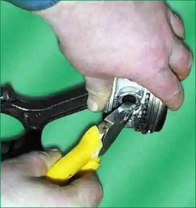
- Remove the circlips from both sides of the piston.
- Press out the piston pins with a special tool.
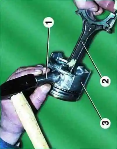
If the tool is not available, the piston pins can be knocked out with light blows of a hammer through the mandrel 1.
Remove connecting rod 2 from piston 3.
- In the same way, remove the remaining pistons from the connecting rods.
- After disassembly, wash all parts in gasoline.
Clean the pistons from carbon deposits.
Clean the piston ring grooves with an old piston ring or a broken ring.
Dimensional groups of pistons, connecting rods and pins

Inspection, check and repair
Inspect the pistons.
If they have scuff marks, traces of burnout, deep scratches, replace the pistons.
Measure the piston diameter. If it is less than 91.9 mm, replace the piston.
The piston diameter is measured in a plane perpendicular to the piston pin axis, 8.0 mm below the piston pin axis.
The piston is installed in the cylinder with a clearance of 0.024–0.048 mm.
In order to ensure the clearance, the pistons are divided by diameter into five size groups A, B, C, D and E.
The letter marking is stamped on the piston crown.
When selecting a piston to a cylinder, the clearance indicated above must be ensured.
The maximum allowable clearance between the piston and the cylinder is 0.25 mm.
The clearance between the piston and the cylinder can be determined by measuring the piston and the cylinder.
Pistons of two repair sizes are supplied as spare parts: with a diameter increased by 0.5 mm and by 1.0 mm.
On one of the bosses under the piston pin, the inscription "406" (piston of nominal size), "406AP" (piston increased by 0.5 mm), "406BR" (piston increased by 1.0 mm) is cast.
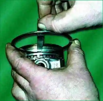
Measure the gap between the piston ring and the groove on the piston at several places around the circumference of the piston.
The gap should be between 0.05–0.087 mm for compression rings and 0.115–0.365 mm for the oil scraper ring.
If the clearances are greater than specified, the rings or pistons must be replaced.
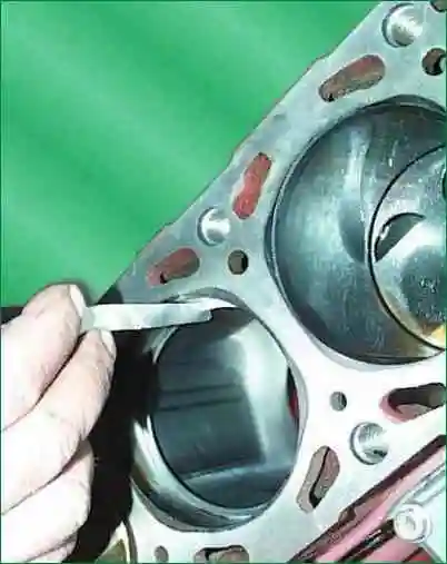
Measure the gaps in the locks of the piston rings.
To do this, insert the ring into the cylinder and advance the piston like a mandrel so that the ring fits in the cylinder evenly, without distortion.
Measure the gap in the ring lock with a feeler gauge, it should be within 0.3–0.6 mm for compression rings and 0.5–1.0 mm for oil scraper discs.
If the gap exceeds the specified, replace the ring.
If the gap is smaller, you can file off the ends of the ring with a file clamped in a vise.
In this case, the ring is moved up and down the file.
Check the fit of the piston pin in the upper end of the connecting rod.
The clearance between the pin and the bushing of the upper end of the connecting rod should be between 0.0045-0.0095 mm.
Pistons, pistons and connecting rods divided into four size groups and marked with paint.
The pin is marked on the inner surface from one end, the connecting rod is marked on the rod, the piston is on the bottom surface of one of the bosses, or a Roman numeral is knocked out on the piston bottom.
Dimensional groups of pistons, connecting rods and pins are shown in the table.
Lightly lubricate the piston pin with engine oil and insert into the upper end of the connecting rod.
The finger should enter the head from the effort of the thumb evenly, without jamming.
The connecting rod should turn on the finger under its own weight from a horizontal position.
The pin must not extend or fall out of the connecting rod head under its own weight when the connecting rod is rotated so that the pin is vertical.
Piston pin and connecting rod must be the same or adjacent size groups.
- Pistons with piston rings, pins and connecting rod assemblies are selected by weight. The difference in weight for one engine should be no more than 10 g.
- Inspect the connecting rod bearings. If they have scuffs, risks, chipping, etc., they must be replaced.
- Install the caps on the connecting rods and measure the diameter of the hole in the bottom end of the connecting rod. Nominal hole diameter 60 +0.019 mm, maximum allowable - 60.03 mm.
If the measured diameter exceeds the limit, replace the connecting rod with a cap.
Measure the diameter of the hole in the connecting rod bushing.
Nominal hole diameter 22 +0.007 and 22 -0.003 mm, maximum allowable - 22.01 mm.
If the measured diameter exceeds the limit, replace the connecting rod.
The dimensions of the connecting rod and piston group are shown in the table.
Build and install
Assemble piston 4 with connecting rod 3. Before doing this, heat the piston to a temperature of 60-80°C.
Then, quickly insert the connecting rod into the piston so that the inscription: "Front" on the piston and the protrusion "A" on the connecting rod are on the same side, and press in the piston pin 6.
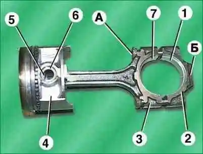
Install retaining rings 5.
Put the piston rings onto the piston using a puller.
On the upper compression ring there is an inscription: "Top", the ring must be installed on the piston with this inscription to the bottom of the piston.
There is a groove on the inner side of the lower compression ring, the ring must be installed with this groove upwards to the piston bottom.
Insert bushing 7 into the lower head of the connecting rod, while the locking lug on the bushing must fit into the recess in the lower head of the piston.
Insert bushing 1 into connecting rod cap 2, making sure the locking lug of the bushing fits into the recess in the cap.
Lubricate cylinder, piston 4, crankshaft journal and bearings 1 and 7 with engine oil.
Turn the piston rings so that the compression ring locks are at an angle of 180° to each other, the scraper ring disc locks are also at an angle of 180° to each other and at 90° to the compression ring locks, the oil scraper ring expander lock is at an angle of 45° to the lock of one of the oil scraper discs.
Turn the crankshaft so that the connecting rod journal of the cylinder in which the piston is installed is at the n.m.t.
Insert the piston with the connecting rod into the cylinder, while the inscription: "Front" on the piston boss must face the front of the engine (towards the camshaft drive).
In order not to damage the cylinder mirror, it is recommended to put bushings made of soft material on the connecting rod bolts (for example, pieces of rubber or plastic hoses).
Using a special crimp, compress the piston rings and lightly push the piston into the cylinder with a hammer handle, while the crimp must be firmly pressed against the block, otherwise the piston rings can be broken.
Move the piston down so that the lower head of the connecting rod sits on the connecting rod journal of the crankshaft, remove the hose trimmings from the connecting rod bolts.
Install the connecting rod cover 2 on the connecting rod bolts, with the step B on the connecting rod cover on the same side as the protrusion A on the lower connecting rod head, and the cylinder numbers stamped on the connecting rod and the cover located on one side.
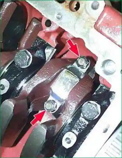
- Install the connecting rod bolt nuts and tighten to 68-75 Nm (6.8-7.5 kgfm).
- In the same way, install the remaining pistons with connecting rods.
- Turn the crankshaft several times, it should rotate easily, without jamming.
- Install the oil pump, oil sump and cylinder head.
Let's take a closer look:
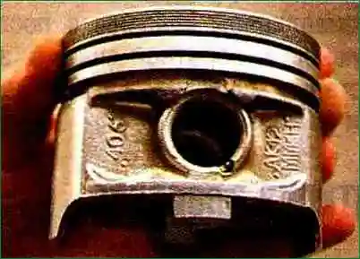
The designation "406" on the piston indicates that the piston is for the ZMZ-406 engine
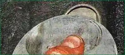
When repairing with cylinder boring, the required clearances are provided in the process of boring and honing for pre-purchased pistons of repair size.
Two designations are embossed on the piston crown. According to the letter applied with paint, on the new block, the piston approaches the cylinder.
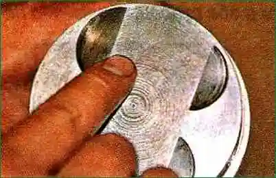
The diameters of the holes in the piston bosses, the connecting rod head and the outer diameters of the piston pin are divided into four groups, marked with paint: I - white, II - green, III - yellow, IV - red.
Roman numeral indicates required finger group.
On the fingers, the group number is indicated by paint on the inner surface or ends. It must match the group indicated on the piston.
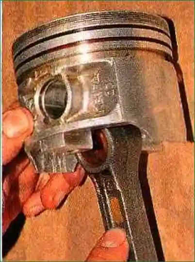
On the connecting rod, the group number is also indicated by paint. It must either match or be adjacent to the group finger.
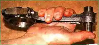
The finger lubricated with engine oil should move with little effort in the connecting rod head, but not fall out of it.
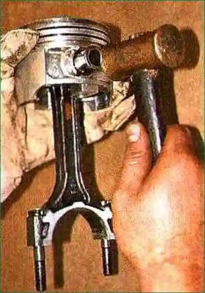
We heat the piston to a temperature of 60 - 80 ° C. We insert the connecting rod head between the piston bosses and press in the lubricated piston pin.
If there is no fixture, you can press the finger with a copper or ordinary hammer, through a soft metal mandrel, holding the piston in weight.
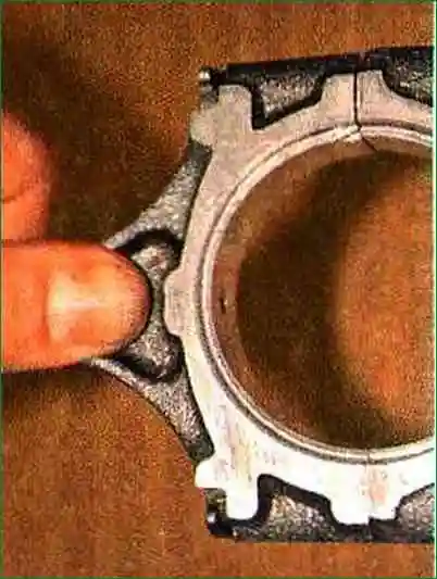
After assembly, the tab on the bottom end of the connecting rod should be on the same side as the "FRONT" lettering on the piston.
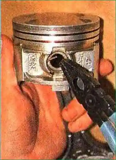
We fix the piston pin on both sides with retaining rings
We put the rings on the piston.
Checking the piston rings.
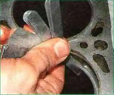
Compression rings installed in the cylinder to a depth of 20 - 30 mm should have a gap in the lock - 0.3 - 0.6 mm, oil scraper - 0.5 - 1 mm.
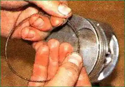
Spreading the lock of the oil scraper ring expander, we put it on the piston in the lower groove, and reduce the lock.
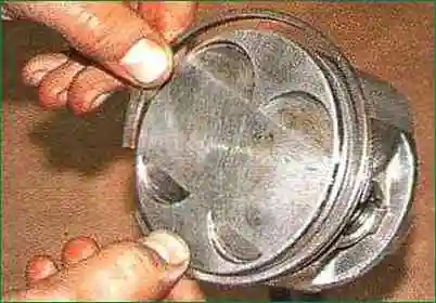
We put an oil scraper ring on the expander.
The angle between the locks of the ring and the expander with a one-piece ring is 45˚, with a detachable ring it is 90˚.
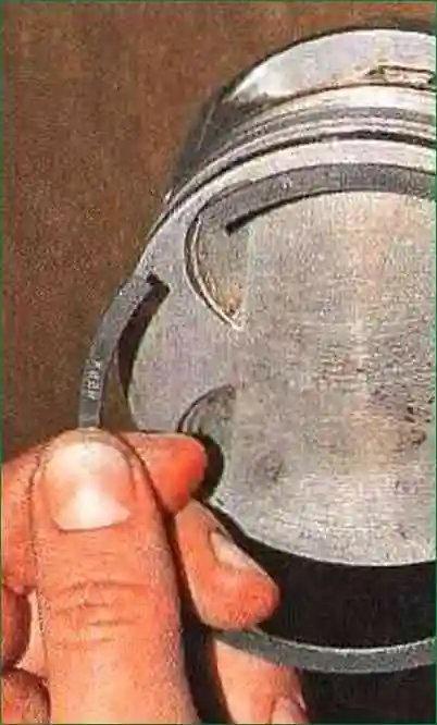
We put on the lower compression ring with the inscription "Top" to the piston bottom
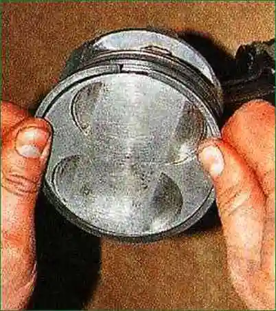
Last put on the top compression ring.
Turn the rings so that the locks of the upper compression rings are on opposite sides of the piston.


