Chain camshaft drive, two-stage
Includes: crankshaft sprocket (23 teeth), intermediate shaft driven and driven sprockets (38 and 19 teeth), camshaft sprockets (23 teeth), two reinforced bushing chains (72 links - lower and 92 links - upper ), hydraulic tensioners, tensioner arms, and chain guides.
The tension of the chain of each stage is carried out by hydraulic tensioners located: the lower chain - in the chain cover, the upper chain - in the cylinder head.
Withdrawal
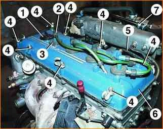
Remove oil filler plug 1.
Remove the 2 spark plug tips with the 3 high voltage wire seals and wires.
Disconnect hose 5 and tube 7 for crankcase ventilation from the fittings on cover 6 of the cylinder head.
Unscrew the eight bolts 4 and remove the cylinder head cover 6 with the cover gasket.
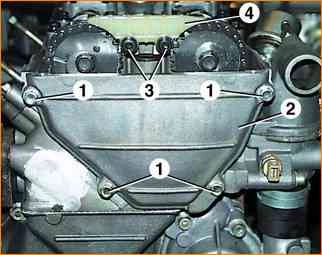
Unscrew the four bolts 1 and remove the front cover 2 of the cylinder head, being careful not to damage the gasket.
Unscrew bolts 3 and remove plastic chain guide 4.
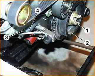
Set the piston of the 1st cylinder to the top dead center (TDC) of the compression stroke.
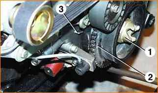
To do this, turn the crankshaft by ratchet 1 so that mark 2 on the crankshaft pulley coincides with protrusion 3 on the cover.
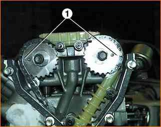
In this case, marks 1 on the camshaft sprockets should be located horizontally at the level of the upper plane of the cylinder head and directed in opposite directions.
After installing the piston of the 1st cylinder in the i.m.t. Do not turn the camshafts, crankshaft and intermediate shaft.
Remove the water pump.
Remove the generator.
Unscrew ratchet 1, holding the crankshaft from turning, inserting a screwdriver between the flywheel teeth and resting it against the pin for installing the clutch housing.
Using a puller, press pulley 2 from the crankshaft.
Unscrew the bolts 3 and remove the cover 4 of the lower chain hydraulic tensioner with the gasket.
Remove the cover carefully, as it is affected by the force of the hydraulic tensioner spring.
Then remove the hydraulic tensioner.
Unscrew the crankcase mounting bolts and nuts, remove the crankcase and crankcase gasket.
Unscrew the seven bolts and remove the chain cover.
Remove the cover carefully so as not to damage the front crankshaft oil seal installed in it, the cover gaskets and the cylinder head gasket.
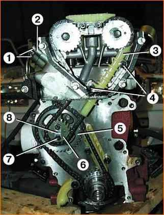
Unscrew bolts 1 and remove cover 2 of the upper chain hydraulic tensioner.
The cover must be removed carefully, as it is affected by the force of the hydraulic tensioner spring.
Then remove the hydraulic tensioner.
Unscrew bolts 4 and remove chain guide 3 upwards.
Bend the ends of the locking plate 8 and unscrew the bolts 7, while holding the intermediate shaft from turning by inserting a screwdriver into the hole of the gear 5.
Remove gear 6 by inserting a screwdriver between gears 5 and 6 and pressing it against gear 6 like a lever.
Remove gear 6 from the upper chain and then remove the chain by pulling it upward.
Remove gear 5 from the intermediate shaft and remove it from the lower chain.
Remove the lower chain from the crankshaft sprocket.
If it is necessary to remove the camshaft gears, you need to unscrew the bolts securing them to the camshaft flanges.
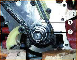
If it is necessary to remove gear 1 from the crankshaft, you must first remove bushing 2 and the rubber sealing ring between bushing 2 and wheel 1.
Then press gear 1 using a puller.
Inspection
After removal, wash the chains and gears in gasoline, wipe and dry.
Inspection there are chains. If there are cracks, chips or significant signs of wear on the chain bushings, replace the chains.
Gears whose teeth are chipped, chipped, or have broken teeth must be replaced.
Replace damaged chain guides.
The tensioner shoes must rotate freely on the axles. If they have cracks, chips or significant wear on the working surface, they need to be replaced.
Installation
If the crankshaft gear was removed, press it onto the crankshaft, install the O-ring and bushing.
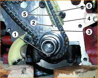
Install key 1 into the groove on the crankshaft.
Rotate the crankshaft so that mark 3 on the crankshaft gear coincides with mark 2 on the cylinder block.
In this case, the piston of the 1st cylinder will take the TDC position.
Install the chain guide 4, but do not tighten the guide bolts 5.
Place chain 6 on the crankshaft gear, having previously lubricated it with engine oil.
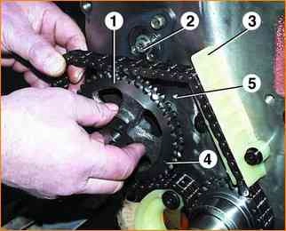
Place the chain on the driven gear 1 and install it on the intermediate shaft 2 so that the wheel alignment pin fits into the hole in the intermediate shaft.
In this case, mark 4 on the gear must coincide with mark 5 on the cylinder block, and the chain branch passing through damper 3 must be tensioned.
Install the drive gear of the intermediate shaft so that its alignment pin fits into the hole on the driven gear.
Tighten the two bolts securing the intermediate shaft gears, placing a locking plate under them.
Tighten the bolts to a torque of 22–25 Nm (2.2–2.5 kgf m) and secure them by bending the edges of the locking plate on the edge of the bolt heads.
After installing the chain, do not turn the intermediate and crankshafts.
Press the tensioner shoe, tighten the chain and check the alignment of the marks on the gears and the cylinder block.
Tighten the chain guide mounting bolts.
Lubricate the upper chain with engine oil and then put it on the drive gear of the intermediate shaft, passing it through the hole in the cylinder head.
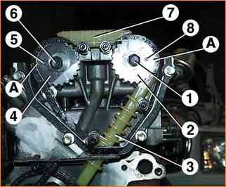
If gear 2 is installed on the camshaft, unscrew bolt 1 and remove gear 2 from the camshaft.
Put the chain on gear 2 and, slightly turning the exhaust camshaft clockwise, install gear 2 with the chain on it.
In this case, pin 8 of the camshaft should fit into the hole of the gear.
Tighten bolt 1.
You need to turn the camshaft using a key using the square on the camshaft.
Then, slightly turn the camshaft counterclockwise to tighten the chain.
The intermediate and crankshafts should not turn.
The “A” mark must coincide with the upper plane of the block head.
Unscrew bolt 6 and remove gear 4 from the intake camshaft.
Place the chain on wheel 4 and install wheel 4 with the chain on the camshaft, slightly turning the camshaft clockwise.
Pin 5 of the camshaft must fit into the hole of the gear.
Turn the chain slightly by turning the camshaft counterclockwise.
The “A” mark on gear 4 should coincide with the upper plane of the block head.
The remaining shafts should not rotate.
Tighten bolt 6. Tighten bolts 1 and 6 to a torque of 46–74 Nm (4.6–7.4 kgf m), holding the camshafts from turning with a wrench using the squares.
Install damper 3 by pushing it into the hole in the block head. Install damper 7.
Install the chain cover and water pump. At the same time, apply a thin layer of Hermesil or similar sealant to the surfaces of the cover adjacent to the cylinder block and the cylinder head.
When installing the chain cover, be careful not to damage the crankshaft oil seal.
Install hydraulic tensioners for the upper and lower chains.
Install the crankshaft pulley.
Tighten the ratchet and tighten to a torque of 104–128 Nm (10.4–12.8 kgf·m), holding the crankshaft from turning, inserting a screwdriver into the teeth of the flywheel ring and resting it against the clutch housing mounting pin.
When the ratchet is tightened, the flywheel pulley is pressed onto the crankshaft.
Turn the crankshaft two turns using the ratchet and install it in position position of v.m.t. piston 1st cylinder.
Check that the labels match.
Install the front cylinder head cover by applying a layer of Hermesil sealant to the surface of the cover adjacent to the cylinder head.
Tighten the cover mounting bolts to a torque of 12–18 Nm (1.2–1.8 kgf m).
Install generator.


