A high-pressure fuel pump (HPF) of the “Compact-40” type with an electronic control system (ECS) assembled with an actuator mechanism, a fuel priming pump and a damper clutch is shown in Figure 1
Designation of fuel injection pump with ESU used on YaMZ-6583.10 engines: full 179.1111002-30, conditional 179.2-30.
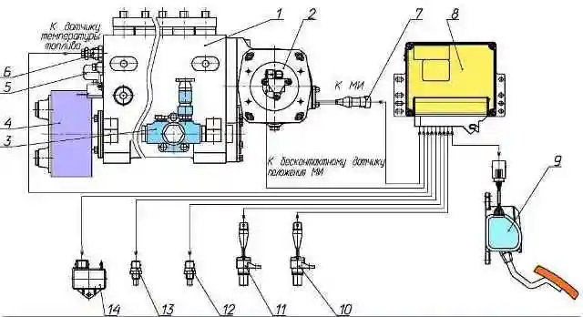
Injection pump designation without ESU: 179.1111005.
The main parameters and characteristics of the injection pump with ECS are given in the table.
Injection pump design and operation
With the high-pressure fuel pump 1, the actuator mechanism (MI) 2, the fuel priming pump (TPP) 3 and the damper clutch 4 are combined in one unit (Fig. 1).
The injection pump, consisting of sections (individual pumping elements) located in a common housing, is installed in the engine camber between the rows of cylinders.
The number of injection pump sections corresponds to the number of engine cylinders.
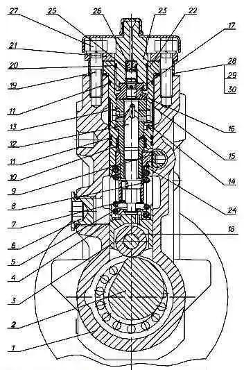
Section of the high pressure fuel pump: 1 - pump housing; 2 - cam shaft; 3 - pusher; 4 - bottom pusher spring plate; 5 - pusher spring; 6 - plug; 7 - spring ring; 8 - rotary bushing; 9 - rack; 10,11, 20 - sealing ring; 12 - plunger; 13 - plunger bushing; 14 - pin; 15 - screen; 16 - discharge valve seat; 17 - discharge valve; 18 - pusher roller; 19 - hairpin; 21 - pressure flange; 22 - section body; 23 - fitting; 24 - upper plate; 25 - discharge valve spring; 26 - valve stop; 27 - nut; 28,29,30 - gaskets
The design of the injection pump section is shown in Figure 2.
In the housing 1 of the injection pump there are housings of sections 22 with plunger pairs, injection valves, plunger pushers 3 and fuel fittings 23, to which high-pressure fuel lines are connected.
Plunger 12 and plunger sleeve 13, discharge valve seat 16 and discharge valve 17 are precision pairs, which can only be replaced as a complete set.
The plunger bushing is fixed in a certain position with a pin 14 pressed into the section body.
The plunger is driven by cam shaft 2 through a roller tappet.
The pusher spring 5, through the lower pusher spring plate 4, constantly presses the pusher roller to the cam.
The plunger pushers, which have flats on the side surfaces, are kept from turning by clamps pressed into the injection pump housing.
The design of the plunger pair allows you to dispense fuel by changing the moment of start and end of supply.
To change the amount and moment of the start of fuel supply, the plunger in the bushing is turned by a rotary bushing 8, which engages with the fuel pump rack 9.
Adjustment of the uniformity of fuel supply at maximum mode by each section of the injection pump is carried out by rotating the section body with loosened nuts 27 securing the sections.
Changing the start of fuel supply depending on its value (engine load) is ensured by control edges made at the end of the plunger.
The section works as follows.
When the plunger moves downward under the action of a spring, fuel under a slight pressure created by the fuel priming pump enters through the longitudinal channel of the injection pump housing into the space above the plunger.
As the plunger moves upward, fuel enters the high-pressure fuel line through the discharge valve and is bypassed into the fuel supply channel until the end edge of the plunger closes the inlet hole of the plunger sleeve.
With further upward movement of the plunger, the fuel pressure in the space above the plunger increases sharply.
When the pressure reaches a value exceeding the injector spring force, the injector needle will rise and the process of injecting fuel into the engine cylinder will begin.
As the plunger moves upward further, the spiral edges of the plunger open shut-off holes in the bushing, which causes a sharp drop in fuel pressure in the fuel line.
At the same time, the discharge valve, lowering into the seat under the action of the spring, increases the volume in the fuel line between the nozzle and the valve.
This ensures a clearer end of fuel injection and unloads the high pressure fuel line.
On the inner surface of the bushing there is a The nzher has an annular groove, and in the wall there is a hole for removing fuel that has leaked through the gap in the plunger pair.
The gaps between the plunger bushing and the section body, the section body and the injection pump body are sealed with rubber O-rings 10, 11, 20.
From the cavity around the plunger bushing, the leaked fuel flows through the groove on the plunger bushing into the fuel channel of the injection pump housing and then through the bypass valve through the fuel line into the fuel tank.
In the lower part of the injection pump housing there is a cam shaft rotating in tapered roller bearings. Depending on the injection pump model, it has one or two intermediate supports.
The cam shaft is installed with an axial tension (0.01-0.07) mm, which is ensured by adjusting shims installed between the bearing cover and the injection pump housing.
The sections are connected to the actuator through the fuel pump rack, which moves in guide bushings pressed into the injection pump housing.
The end of the rail protruding from the housing is protected by the rail cover 5 (Fig. 1).
Main parameters and characteristics of fuel injection pump with ECS
Parameter name - Value
Number of sections 8
Plunger diameter 12 mm
Full plunger stroke 14 mm
Camshaft rotation direction (drive side) - Clockwise (right)
Section operating order (drive side) 1-3-6-2-4-5-7-8
Rated camshaft speed 950 min -1
Camshaft rotation speed corresponding to maximum torque mode 600 min -1
Camshaft rotation speed at minimum idle speed 300 min -1
Lubrication method - centralized from the engine lubrication system
Allowable roll angles, no more:
- - longitudinal 35º
- - transverse 25º
The actuator mechanism is an electromagnet located in a housing attached to the fuel injection pump housing.
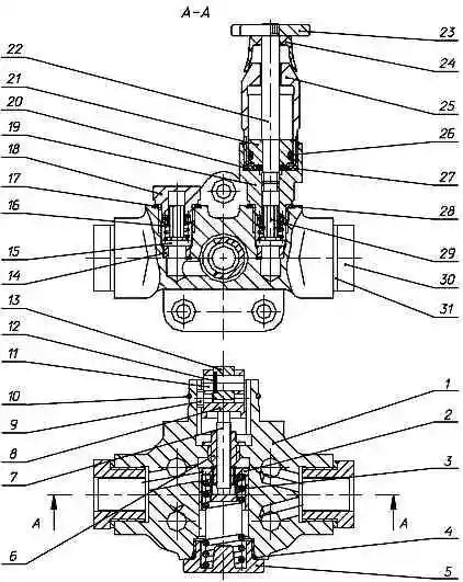
Fuel priming pump: 1 - housing; 2 - piston; 3 - piston spring; 4, 20, 26, 27 - sealing ring; 5 - spring plug; 6 - rod bushing; 7 - pusher rod; 8 - piston pusher; 9 - pusher block; 10 - pusher retaining ring; 11 - roller axis; 12 - locking ring; 13 - pusher roller; 14 - valve seat; 15 - discharge valve; 16 - valve spring; 17.28 - washer; 18 - valve plug; 19 - cylinder body; 21 - pump piston; 22 - rod; 23 - handle; 24 - protective cap; 25 - cylinder; 29 - suction valve; 30 - screwdriver; 31 - gasket
The electromagnet, receiving a command from the electronic control unit, moves the fuel pump rack to the specified position through a system of levers.
When the ESU is turned off, the spring associated with the rack moves it to the feed off position.
Fuel priming pump 3 (Fig. 3) is a piston type, double-acting, designed to supply fuel from the fuel tank through coarse and fine fuel filters to the injection pump.
The performance of the fuel injection pump significantly exceeds the performance of the injection pump, which guarantees the stability of the fuel supply process from cycle to cycle.
The TPN device is shown in Figure 3.
The fuel pump is mounted on the injection pump housing and is driven by the double cam of the camshaft.
The body of the fuel pump 1 contains: TPN piston 2, piston spring 3, fixed by spring plug 5, pusher rod bushing 6 with pusher rod 7, piston pusher 8.
Four valve seats 14 are pressed into the fuel pump housing, to which the fuel pump valves are pressed by valve springs 16, of which valve 29 is suction, and valve 15 is discharge.
The cavity of the TPN housing, in which the piston moves, is connected by channels to the valve cavities.
The piston is driven by a pusher through a rod. The pusher roller 13 rotates on the floating axis of the roller 11.
The roller and axle are fixed with the pusher locking ring 10.
Pusher block 9 protects the pusher from turning.
The pusher rod bushing, which serves as a guide for the rod, is screwed into the TPN body using special glue.
The bushing and rod form a precision pair, which can only be replaced as a complete set.
A manual fuel pump is installed above the suction cavity of the fuel pump, the structure of which is also shown in Figure 3.
This pump is used to remove air from the fuel system before starting the engine and to fill the low pressure line with fuel after maintenance of the power system.
To activate it, it is necessary to unscrew the rod 22 with the piston 20 from the cylinder body 19 by the handle 23 and bleed the engine fuel system.
Damper coupling
The injection pump is equipped with a damper coupling designed to protect the mechanisms from destruction. It is installed on the conical surface of the front end of the cam shaft with tension created by the ring nut.
The damper coupling is secured with a key against rotation.
The damper coupling is a non-separable design with a flywheel that rotates freely in a special high-viscosity fluid.
Dents on the damper coupling body can damage it.
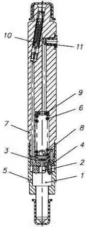
Injector 51-21 (Fig. 4), which is part of the fuel equipment, is a closed-type injector with a multi-jet atomizer and hydraulic needle lift control.
The nozzle parts are assembled in the nozzle body 7. A spacer 3 and the nozzle body 1, inside of which is located the locking needle of the nozzle 2, are attached to the lower end of the nozzle with the nozzle nut 5.
The relative position of the nozzle body, spacer and atomizer body is determined by pins 4 pressed into the spacer.
The atomizer body and the atomizer needle are a precision pair.
The injection start pressure is adjusted using a set of adjusting washers 9.
Fuel is supplied directly to the nozzle body fitting through slot filter 10.
Fuel leaked through the gap between the needle and the nozzle body is discharged through a threaded hole in the upper part of the nozzle body.
The injector is installed in the cylinder head cup. A corrugated washer is installed under the end of the nozzle nut to seal against gas breakthrough.
The nozzle is equipped with a spray assembly, model DLLA 160 P from BOSCH.